Control device

Active Publication Date: 2021-05-06
HITACHI ASTEMO LTD
View PDF0 Cites 1 Cited by
  • Summary
  • Abstract
  • Description
  • Claims
  • Application Information

AI Technical Summary

Benefits of technology

The technical effect of this patent is to reduce the loss of power during power conversion.

Problems solved by technology

Examples of loss generated in the DC-DC converter include switching loss generated by a switching operation and resistance loss (copper loss) generated in a transformer and a semiconductor switch element.

Method used


Image

  • Control device
  • Control device
  • Control device

Examples


first embodiment

(Configuration of Vehicle Power Supply)

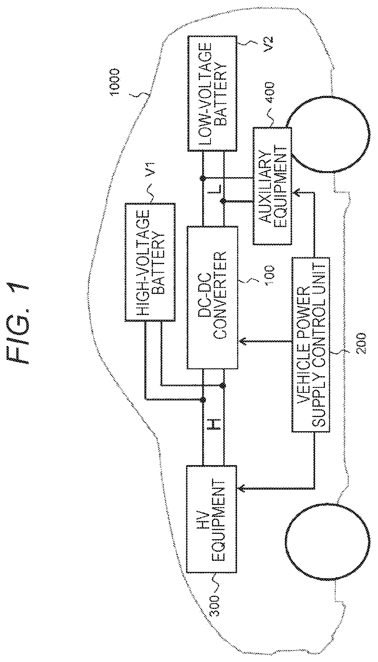
[0022]FIG. 1 illustrates a configuration of a vehicle power supply according to one embodiment of the present invention. As illustrated in FIG. 1, the vehicle power supply according to the present embodiment is a power supply system that is mounted on a vehicle 1000 and mutually performs power conversion between a high-voltage battery V1 and a low-voltage battery V2 by using a DC-DC converter 100. Hereinafter, a low-voltage side of the DC-DC converter 100, that is, a side connected to the low-voltage battery V2 is referred to as an “L side”, and a high-voltage side of the DC-DC converter 100, that is, a side connected to the high-voltage battery V1 is referred to as an “H side”.

[0023]One end of the low-voltage battery V2 is connected to one L-side end of the DC-DC converter 100, and the other end of the low-voltage battery V2 is connected to the other L-side end of the DC-DC converter 100. One end of auxiliary equipment 400 such as an air condi...

second embodiment

[0089]Next, a second embodiment of the present invention will be described. In the present embodiment, an example in which a magnetic flux density command value setting unit 74 of a switching carrier frequency setting unit 70 changes a magnetic flux density command value Bref in accordance with a temperature of a transformer 20 will be described.

[0090]FIG. 6 illustrates a basic circuit configuration of a DC-DC converter 100 according to the second embodiment of the present invention. As illustrated in FIG. 6, the DC-DC converter 100 of the present embodiment has a configuration similar to that described in the first embodiment except for that a temperature detector 43 for detecting the temperature of the transformer 20 is provided close to the transformer 20.

[0091]In the present embodiment, the temperature detector 43 detects the temperature of the transformer 20 and supplies the detected value to the control circuit 50. The detected value of the transformer temperature supplied fro...

third embodiment

[0094]Next, a third embodiment of the present invention will be described. In the present embodiment, an example in which a magnetic flux density command value setting unit 74 of a switching carrier frequency setting unit 70 changes a magnetic flux density command value Bref in accordance with an output current from a DC-DC converter 100 will be described.

[0095]FIG. 8 illustrates a basic circuit configuration of a DC-DC converter 100 according to the third embodiment of the present invention. As illustrated in FIG. 8, the DC-DC converter 100 of the present embodiment has a configuration similar to that described in the first embodiment except for that a current detector 44 that detects an output current of the DC-DC converter 100 output from an output circuit 30 to a low-voltage battery V2 is provided between the output circuit 30 and the low-voltage battery V2.

[0096]In the present embodiment, the current detector 44 detects an output current from the output circuit 30 and supplies ...


PUM


Abstract

A switching loss of a power conversion device is sufficiently reduced. A DC-DC converter includes a switching circuit that converts input first DC power into AC power, a transformer that performs voltage conversion of the AC power, and an output circuit that converts the AC power subjected to the voltage conversion by the transformer into second DC power. The control circuit that controls the DC-DC converter calculates a magnetic flux density value B of the transformer and controls a drive frequency of the switching circuit based on the calculated magnetic flux density value B.

Description

TECHNICAL FIELD[0001]The present invention relates to a control device used for controlling a power conversion device.BACKGROUND ART[0002]In recent years, against the background of depletion of fossil fuels and global environmental problems, automobiles that run using electric energy, such as hybrid automobiles and electric automobiles, have been attracting more attention and have been put to practical use. Such an automobile that travels using electric energy is provided with a high-voltage battery that supplies electric power to a motor for driving wheels. Furthermore, some of such automobiles are provided with a power conversion device that lowers output power from the high-voltage battery and supplies necessary power to low-voltage electric devices mounted on the automobiles, such as an air conditioner, an audio device, and various electronic control units (ECUs). Such a power conversion device converts input DC power into DC power of a different voltage, and is also called a DC...

Claims


Application Information

Patent Timeline
IPC IPC(8): H02M3/337B60L58/20H02M7/537H02M1/40H02M1/08
CPCH02M3/337B60L58/20H02M7/537H02M2001/0054H02M1/08B60L2210/10B60L2240/525H02M1/40B60L2210/12Y02T10/70Y02T10/72H02M1/0054H02M3/33573H02M3/01
Inventor TANAKA, SHINTAROKUBO, KENJIOUCHI, TAKAYUKISOBU, YUJITAKAHASHI, NAOYA
Owner HITACHI ASTEMO LTD
Why Eureka
Try Eureka