Resonant ballast circuit

Inactive Publication Date: 2008-06-12
FAIRCHILD TAIWAN
View PDF2 Cites 0 Cited by
  • Summary
  • Abstract
  • Description
  • Claims
  • Application Information

AI Technical Summary

Benefits of technology

[0006]An objective of the present invention is to provide a ballast circuit that can automatically achieve soft switching for reducing the switching losses and improving the efficiency of the ballast circuit.
[0007]Another objective of the present invention is to develop a lower cost circuit with higher performance in efficiency.

Problems solved by technology

Therefore, in recent developments, the improvement of the efficiency and power savings for the ballast of the fluorescent lamps are the major issues. FIG. 1 shows a conventional electronic ballast circuit in series connection with a resonant circuit.
The drawback of this ballast circuit is higher switching losses on the switches 10 and 20.

Method used


Image

  • Resonant ballast circuit
  • Resonant ballast circuit
  • Resonant ballast circuit

Examples


Embodiment Construction

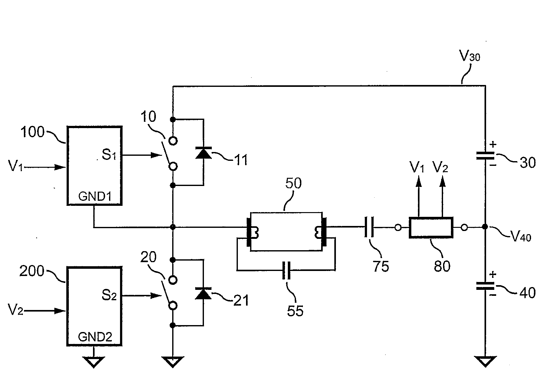
[0016]FIG. 2 shows a schematic circuit of a ballast circuit according to an embodiment of the present invention. A capacitor 75 and a transformer 80 are connected in series to form a resonant circuit. The resonant circuit produces a sine wave current to operate a lamp 50, which is a fluorescent lamp in an embodiment of the present invention. A first switch 10 is coupled to the resonant circuit to supply a first voltage V30 to the resonant circuit. The first switch 10 is controlled by a first switching signal S1. A second switch 20 is coupled to the resonant circuit to supply a second voltage V40 to the resonant circuit. The second switch 20 is controlled by a second switching signal S2. A first winding of the transformer 80 is connected in series with the capacitor 75 to form the resonant circuit.

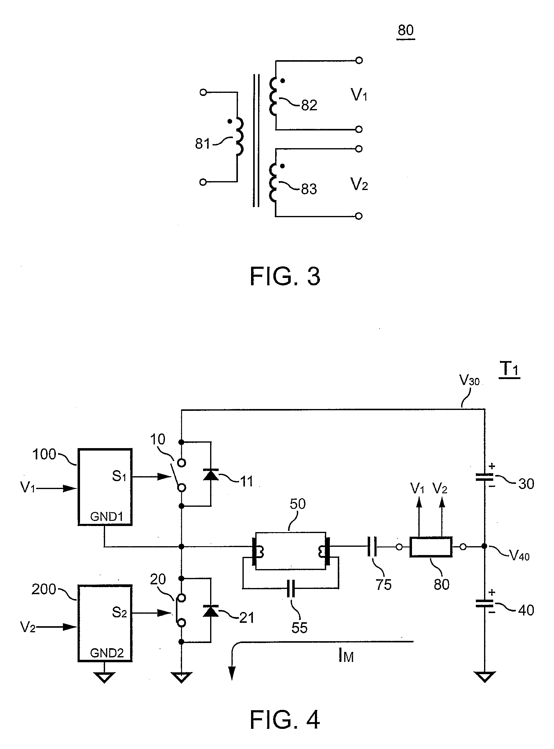
[0017]FIG. 3 shows a plurality of windings of the transformer 80. A second winding 82 and a third winding 83 of the transformer 80 are used for respectively generating a first control signa...


PUM


Abstract

A low cost ballast circuit for fluorescent lamp is provided. A fluorescent lamp is connected in series with a resonant circuit having a transformer. A first switch and a second switch are coupled to switch the resonant circuit. A first winding of the transformer is connected in series with a capacitor to form the resonant circuit. A second winding and a third winding of the transformer are used for generating control signals in response to a switching current of the resonant circuit. The first switch and the second switch are controlled in response to the control signals. Furthermore, soft switching operation for the first switch and the second switch can be achieved by the present invention.

Description

BACKGROUND OF THE INVENTION[0001]1. Field of the Invention[0002]The present invention relates in general to a switching circuit, and more particularly, to a switching circuit of a ballast.[0003]2. Description of Related Art[0004]Fluorescent lamps are one of the most popular light sources in our daily lives. Improving the efficiency of fluorescent lamps saves energy significantly. Therefore, in recent developments, the improvement of the efficiency and power savings for the ballast of the fluorescent lamps are the major issues. FIG. 1 shows a conventional electronic ballast circuit in series connection with a resonant circuit. A half-bridge inverter consists of a first switch 10 and a second switch 20. The two switches 10 and 20 are complementarily switched on and off with 50% duty cycle at a desired switching frequency. The resonant circuit is composed of an inductor 70, a capacitor 75 to operate a fluorescent lamp 50. A capacitor 55 connected in parallel with the fluorescent lamp 5...

Claims


Application Information

Patent Timeline
IPC IPC(8): H01J7/44
CPCH05B41/2856Y10S315/05
Inventor YANG, TA-YUNG
Owner FAIRCHILD TAIWAN
Why Eureka
Try Eureka