

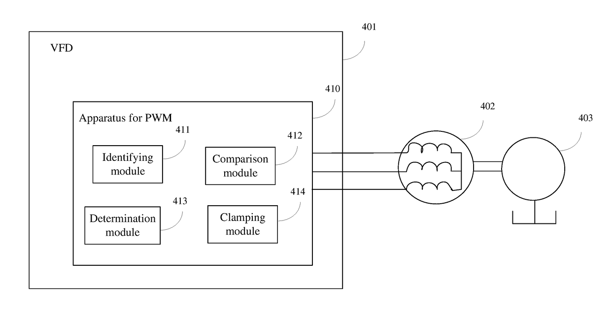
Method and apparatus for pulse-width modulation of a variable-frequency drive
- Summary
- Abstract
- Description
- Claims
- Application Information
AI Technical Summary
Benefits of technology
Problems solved by technology
Method used
Image

Examples
Embodiment Construction
[0015]Embodiments of the present invention are described below by referring to the drawings. Numerous details are described below so that those skilled in the art can understand and realize the present invention. However, it is apparent for those skilled in the art that the realization of the present invention may not include some of the details. In addition, it should be understood that the present invention is not limited to the described specific embodiments. On the contrary, it is contemplated that the present invention can be realized using any combination of the features and elements described below, no matter whether the features and elements relate to different embodiments or not. Therefore, the following aspects, features, embodiments and advantages are only for illustration, and should not be taken as elements of or limitations to the claims, unless explicitly stated otherwise in the claims.
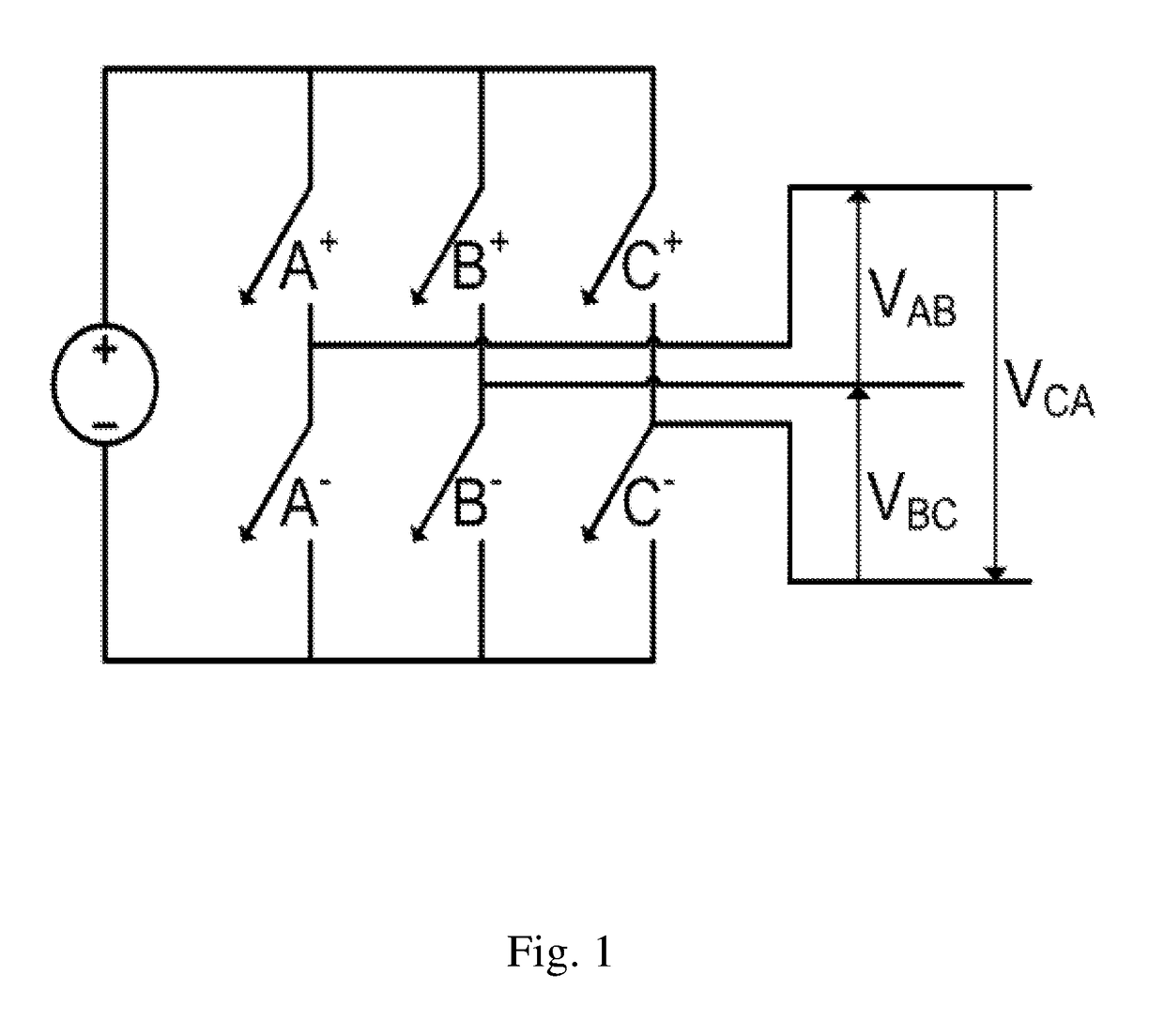
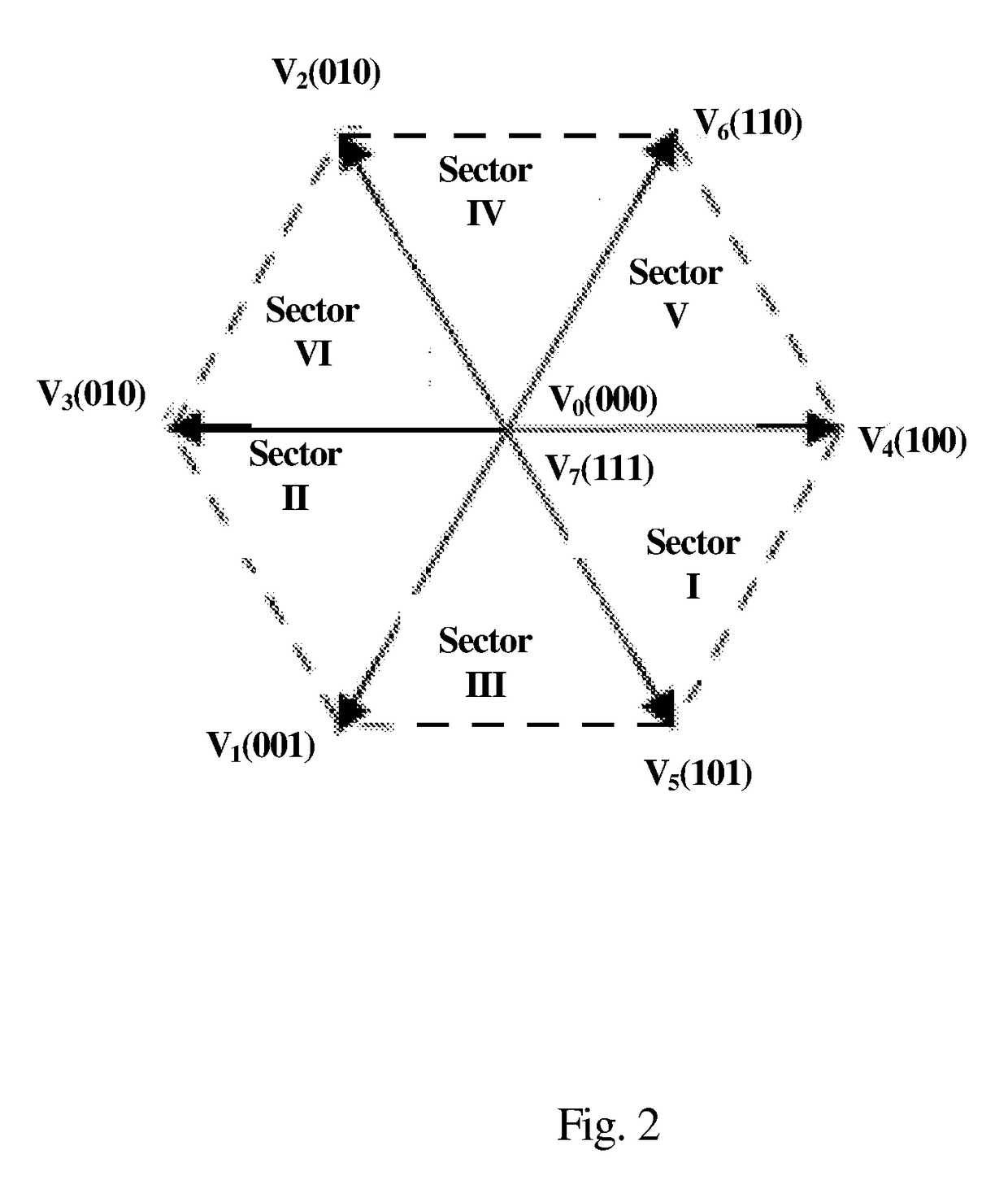
[0016]As known by those skilled in the art, PWM of a VFD refers to driving an AC mo...
PUM
 Abstract
Description
Claims
Application Information