Battery pack temperature control method and device

Active Publication Date: 2019-12-19
LG ENERGY SOLUTION LTD
View PDF0 Cites 3 Cited by
  • Summary
  • Abstract
  • Description
  • Claims
  • Application Information

AI Technical Summary

Benefits of technology

The invention provides a method and device to control the temperature of a battery pack. It uses a PWM signal with a specific duty ratio to increase the temperature of the battery pack at low temperatures. As the temperature increases, the duty ratio is adjusted accordingly to ensure a stable increase in the battery pack temperature. This technology ensures that the battery pack is always operational at the optimal temperature range which results in improved performance and durability.

Problems solved by technology

However, in such an exemplary low temperature state, the battery pack has a problem in that the capacity of the usable battery pack is substantially reduced as the electrolyte increases in viscosity, and the movement of lithium ions moving during the charging / discharging is slowed to deteriorate lifetime, stability, and driving performance of the battery pack.
However, since the heat generating component is driven using the battery pack as a driving source, when the heat generating component is driven for the charging / discharging at an extremely low temperature, it may be used below a preset minimum discharge voltage of the battery pack by the reduced capacity of the battery due to the extremely low temperature.
As a result, permanent damage may occur at the battery pack, resulting in dangerous situations such as explosion and ignition.
In order to solve this problem, although a battery management system (BMS) within the battery pack is controlled to limit the use of the battery pack below the minimum discharge voltage, there is an additional problem in that the driving of the heat generating component is interrupted by the minimum discharge voltage when heat is not sufficiently transferred throughout the battery pack.

Method used


Image

  • Battery pack temperature control method and device
  • Battery pack temperature control method and device
  • Battery pack temperature control method and device

Examples


embodiment 1

[0031]Next, a method for controlling a temperature of a battery pack according to an embodiment of the present invention will be described.

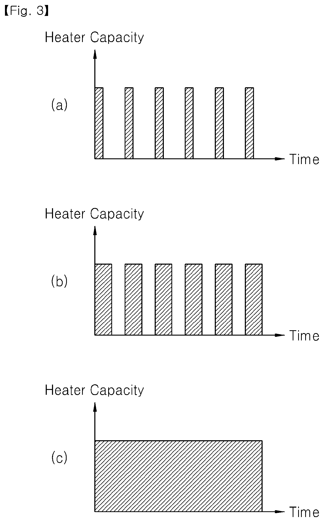
[0032]In the method for controlling the temperature of the battery according to the present invention, when the charging / discharging of the battery pack is performed at a low temperature, a PWM signal having a predetermined duty ratio may be outputted to drive a heat generating unit. Thus, the outputted duty ratio of the PWM signal increases as the battery pack increases in temperature so that a temperature value of the battery stably increases.

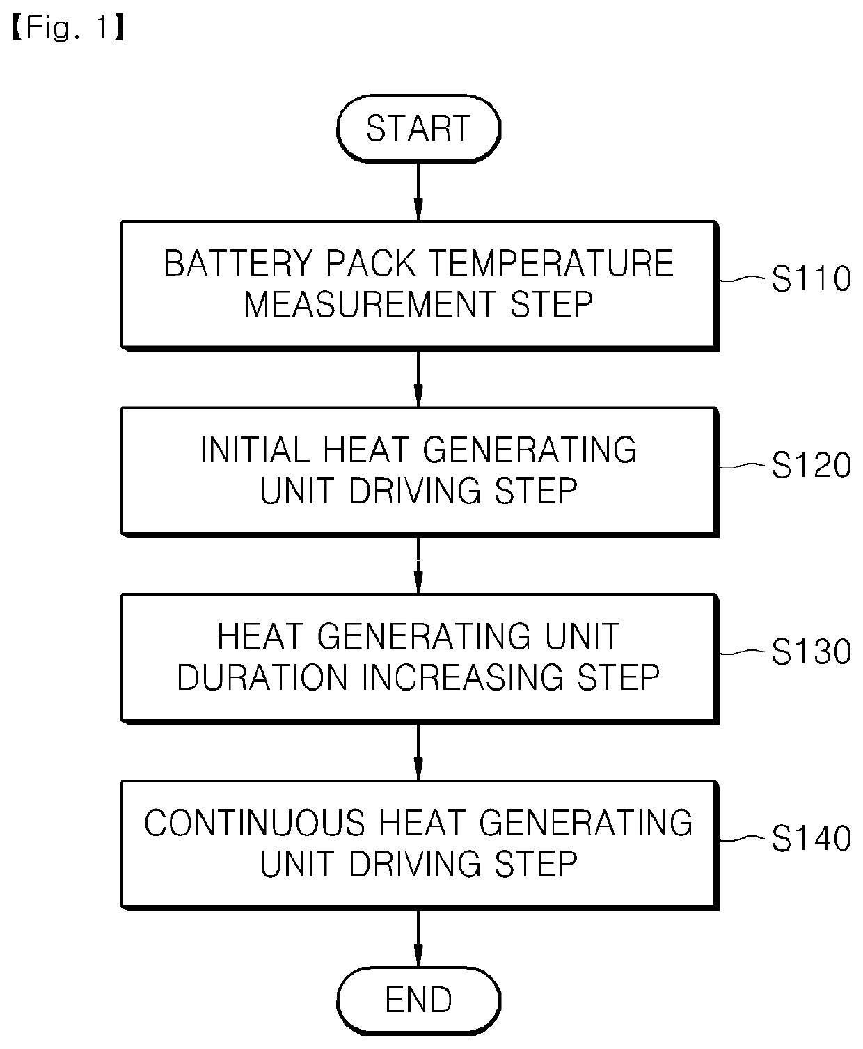
[0033]FIG. 1 is a flowchart illustrating a method for controlling a temperature of a battery pack according to an embodiment of the present invention.

[0034]Referring to FIG. 1, in a method for controlling a temperature of a battery pack according to an embodiment of the present invention, a temperature value of the battery pack is measured before charging / discharging is performed (a battery pack temperatur...

embodiment 2

[0075]Next, an apparatus for controlling a temperature of a battery pack according to an embodiment of the present invention will be described.

[0076]The apparatus for controlling the temperature of the battery pack of the present invention may control a heat generating unit switch to intermittently turn-on / off a heat generating unit attached to the battery pack under an extremely low temperature to stably safely perform charging / discharging of the battery pack.

[0077]FIG. 4 is a block diagram illustrating the apparatus for controlling the temperature of the battery pack according to an embodiment of the present invention.

[0078]Referring to FIG. 4, an apparatus 300 for controlling the temperature of the battery pack according to an embodiment of the present invention includes a heat generating unit 330 surrounding a battery pack 320 constituted by a plurality of battery cells, a heat generating unit switch 340 for turning on / off current supply to the heat generating unit 330, and a BM...


PUM


Abstract

A method and apparatus for controlling a temperature of a battery pack, in which, when the battery pack is in an extremely low temperature state during charging / discharging, a PWM signal having a duty ratio value that increases as the temperature increases is outputted to intermittently drive a heat generating unit so that the battery pack stably increases in temperature.

Description

TECHNICAL FIELD[0001]The present invention relates to a method and apparatus for controlling a temperature of a battery pack, and more particularly, to a method and apparatus for controlling a temperature of a battery pack, in which, when the battery pack is in an extremely low temperature state during charging / discharging, a PWM signal having a duty ratio value that increases as the temperature increases is outputted to intermittently drive a heat generating unit so that the battery pack stably increases in temperature.BACKGROUND ART[0002]A typical battery pack is provided as a chargeable / dischargeable secondary battery. The secondary battery includes a plurality of assemblies, each of which includes a plurality of unit cells.[0003]Also, the cell is constituted by a positive electrode collector, a separator, an active material, an electrolyte, an aluminum thin film layer, and the like. Since the charging / discharging of the battery pack is performed by electrochemical reaction, the ...

Claims


Application Information

Patent Timeline
IPC IPC(8): H01M10/48H01M10/615H01M10/63H01M2/10H01M50/204
CPCH01M2/1016H01M10/48H01M10/615H01M10/63H01M10/625H01M2220/20Y02E60/10H01M50/204H01M10/486H01M2010/4271H01M10/633H01M10/617
Inventor KIM, SEUNG HWANKIM, DONG HYUN
Owner LG ENERGY SOLUTION LTD
Why Eureka
Try Eureka