Battery apparatus

Pending Publication Date: 2022-10-27
MAKITA CORP
View PDF0 Cites 0 Cited by
  • Summary
  • Abstract
  • Description
  • Claims
  • Application Information

AI Technical Summary

Benefits of technology

The patent text describes a way to prevent battery tabs from getting too hot during charging or discharging. By using battery tabs with a larger sheet thickness, the heat generated can be reduced and the risk of an excessive temperature increase can be minimized. This reduces the likelihood of damage to the battery or malfunctions in its performance.

Problems solved by technology

When electric current flows through a battery tab, heat may be generated owing to the electrical resistance of the battery tab, and this heat may cause the temperature of the battery tab to increase.
If the sheet thickness of the battery tab(s) is small (relatively small or relatively thin), then electrical resistance is high (relatively high) and the amount of heat generated at such a location will be relatively large when a large current flows through the battery tab, thereby causing the temperature to rise, possibly excessively, at such a location when a large current flows through the battery tab.
Consequently, it is possible to reduce the likelihood that one or more of the battery tabs (in particular, the battery tabs that conduct relatively large amounts of current) will reach excessively high temperatures, e.g., during a charging or discharging operation of the battery apparatus.

Method used


Image

  • Battery apparatus
  • Battery apparatus
  • Battery apparatus

Examples


working example 1

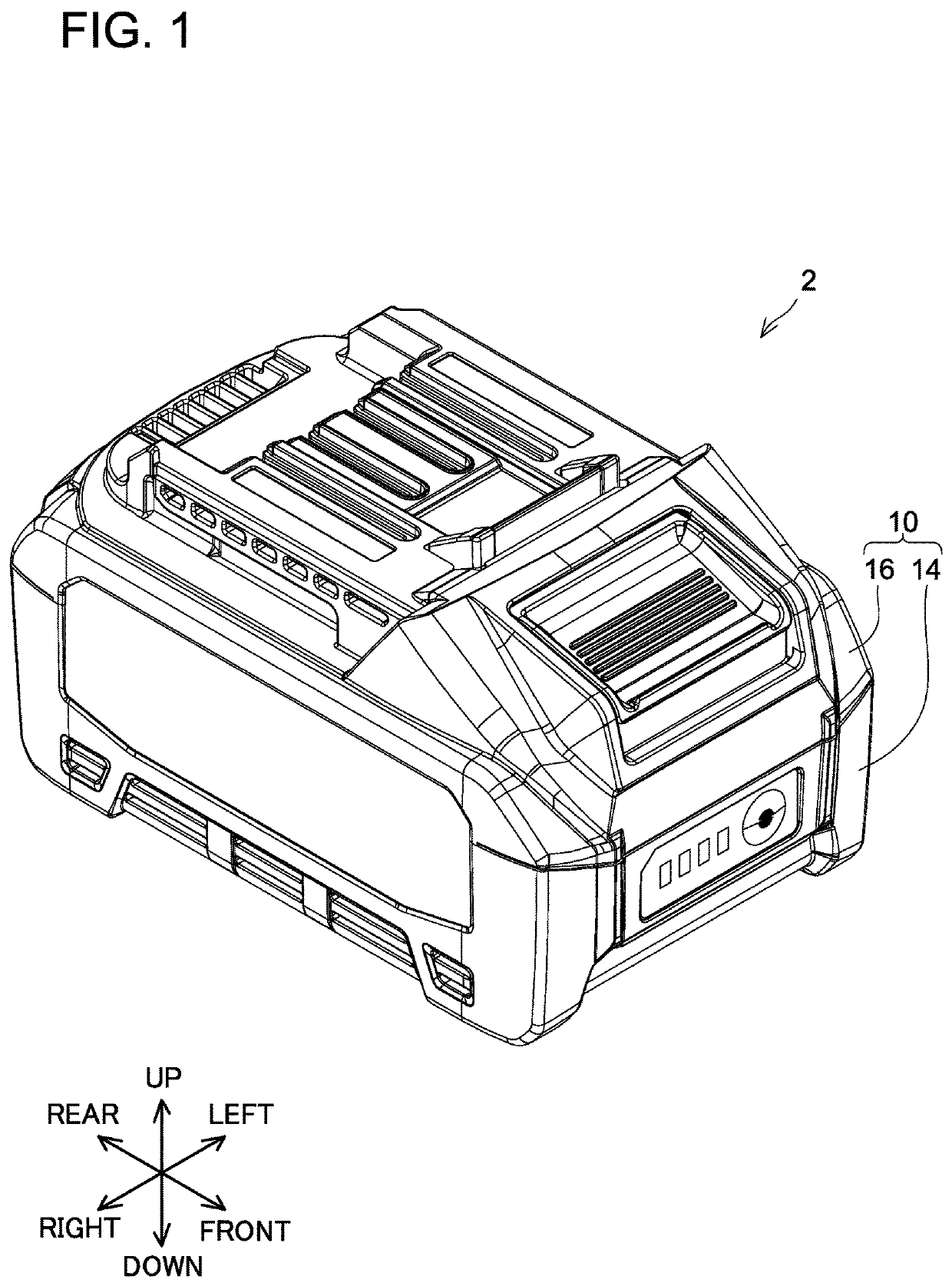
[0055]A battery pack 2 according to the present Working Example 1, which is shown in FIG. 1, is used by being mounted on a battery-pack mount portion (not shown) of electrical equipment (not shown). The electrical equipment may be electrical equipment that runs on electric power supplied from the battery pack 2. The electrical equipment may be, for example, a power tool in which the electric motor of a driver, a drill, or the like serves as the power source, or may be an electric work machine in which the electric motor of a mowing machine (lawn mower), a blower, or the like serves as the power source. Alternatively, the electrical equipment may be electrical equipment that does not have a motor, such as a light, a radio, a speaker, or the like. Alternatively, the electrical equipment may be a charger that supplies electric power to the battery pack 2. The rated (nominal) voltage of the battery pack 2 is, for example, 36 V. The maximum voltage of the battery pack 2 is, for example, ...

working example 2

[0102]A battery pack 202 according to the present Working Example 1, which is shown in FIG. 10, has substantially the same configuration as that of the battery pack 2 of Working Example 1. Hereinbelow, structural elements that are the same as those in the battery pack 2 of Working Example 1 are assigned the same symbols, and detailed explanation thereof is omitted. The rated (nominal) voltage of the battery pack 202 is, for example, 18 V. The maximum voltage of the battery pack 202 is, for example, 20 V. The rated (nominal) capacity of the battery pack 2 is, for example, 4.0 Ah.

[0103]The battery pack 202 comprises the casing (case, housing) 10 and the battery-cell unit 12 (refer to FIG. 11), which is housed in the interior of the casing 10. The casing 10 comprises the lower casing (shell) 14 and the upper casing (shell) 16.

[0104]As shown in FIG. 11, the battery-cell unit 12 comprises: the plurality of battery cells 18 (refer to FIG. 12); the cell holder 20, which is made of a resin ...

modified examples

[0132]The above-described working examples were explained using the battery packs 2, 202 as exemplary embodiments of the battery apparatus of the present teachings; however, the battery apparatus according to the present teachings includes or encompasses other types of battery apparatus, for example, an attachable battery apparatus (portable backpack power supply) in which, for example, shoulder belts, a hip belt, and the like are attached to the battery apparatus so that the user can carry the battery apparatus on his or her back. In such an embodiment, the battery apparatus and the electrical equipment may be electrically connected by, for example, a connection cord (power cord).

[0133]In the above-described embodiments, the battery cell(s) 18 is (are) not limited to having a substantially circular-column shape and may be a so-called rectangular-prism type or may be a laminate type.

[0134]A battery apparatus according to the present teachings may contain a number and type of battery...


PUM


Abstract

A battery apparatus may include: a plurality of battery cells, each of the battery cells having a positive electrode and a negative electrode; and a plurality of battery tabs. Each of the battery tabs has at least one cell-connection part, which is electrically connected to the positive electrode or the negative electrode of a respective one of the plurality of battery cells, and a sheet part, which is integrally formed with the at least one cell-connection part. Each of the battery tabs may be either a first-type battery tab or a second-type battery tab. The sheet thickness of at least one portion of the first-type battery tab may be larger than the sheet thickness of at least one portion of the second-type battery tab.

Description

CROSS-REFERENCE TO RELATED APPLICATION[0001]This application claims priority to Japanese patent application no. 2021-074326 filed on Apr. 26, 2021, the contents of which are fully incorporated herein by reference.TECHNICAL FIELD[0002]The present invention generally relates to a battery apparatus, such as a battery pack, battery cartridge or portable backpack power supply, that may be used to supply current to a power tool, outdoor power equipment, etc.BACKGROUND ART[0003]For example, the battery apparatus is disclosed in Japanese Laid-open Patent Publication 2017-92049 comprises: a plurality of battery cells, each of the battery cells having a positive electrode and a negative electrode; and a plurality of battery tabs, each of the battery tabs having at least one cell-connection part, which is electrically connected to the positive electrode or the negative electrode of a respective one of the battery cells, and a sheet part, which is integrally formed with the at least one cell-co...

Claims


Application Information

Patent Timeline
IPC IPC(8): H01M50/533H01M50/204H01M50/247H01M10/42
CPCH01M50/533H01M50/204H01M50/247H01M10/425H01M2220/30H01M50/503Y02E60/10H01M10/052H01M10/443
Inventor TANAKA, KAZUYA
Owner MAKITA CORP
Why Eureka
Try Eureka