Motor vehicle with battery cooling system

a technology for motor vehicles and cooling systems, applied in batteries, hybrid vehicles, secondary cell details, etc., can solve problems such as toxic or flammable, and achieve the effects of improving the cooling capacity of passive cooling, facilitating integration in the motor vehicle, and improving the maintenan

Active Publication Date: 2016-11-08
AUDI AG
View PDF24 Cites 4 Cited by
  • Summary
  • Abstract
  • Description
  • Claims
  • Application Information

AI Technical Summary

Benefits of technology

[0020]Advantageously, in the motor vehicle according to the invention, a passive cooling element which preferably has cooling fins may be arranged on a supply line of the gas to the pressure accumulator and / or on the pressure accumulator itself. When used for cooling, it is very important that the gas is not hot. When large quantities of cooling gas are consumed, compression can cause the gas to heat up. Passive cooling of the tank or supply lines can help. Such a purely passive cooling is easier to maintain, cheaper and easier to integrate in the motor vehicle, than active cooling, for example when using a chiller. The cooling capacity of the passive cooling can be further improved by routing an existing cooling air flow, for example for cooling components of the engine, also past this passive cooling element.
[0021]As described above, the cooling capacity for the battery module is significantly improved by cooling with compressed air. However, a high cooling capacity is not necessary in many driving situations. Cooling the battery module with ambient air is more energy-efficient than cooling with compressed air. Therefore, it is advantageous if the motor vehicle includes at least one air supply device configured to supply air from the surroundings of the vehicle to the battery module. In driving situations where no intense cooling is necessary, the battery can then be cooled with an air nozzle as an air supply device and thus by the air flow.
[0022]It is also advantageous if in the vehicle according to the invention the battery is cooled by a controlled supply of compressed air. Therefore, the motor vehicle may include a controller which is configured to control the supply of gas from the pressure accumulator to the battery module as a function of at least one output value from at least one sensor. Sufficient cooling of the battery module can then be ensured in all driving situations, while at the same time minimizing the energy expenditure required to compress the gas. The sensor may be a temperature sensor disposed on the battery module, which enables a simple control. For example, the cooling may be activated when the temperature of the battery exceeds a fixed value. On the other hand, the supply of compressed air may also be continuously controllable. The control device can then optimally dose the supplied quantity of compressed depending on the temperature.
[0023]The sensor may also be designed to measure the current output of the battery module. When the battery supplies more current, increased heating results. A direct measurement of the current has the advantage that an increase of the battery temperature must not subsequently be reversed by supplying more compressed air, but that instead an increase in temperature of the battery is avoided. This can further improve the battery life. Of course, several sensors may also be combined. For example, a temperature sensor can ensure that the temperature reliably does not exceed or drop below certain limit temperatures, while a current sensor may prevent large fluctuations in temperature.

Problems solved by technology

Most cooling gases that are already liquid at low pressures, however, are not present in the environment and often toxic or flammable.

Method used


Image

  • Motor vehicle with battery cooling system
  • Motor vehicle with battery cooling system
  • Motor vehicle with battery cooling system

Examples


Embodiment Construction

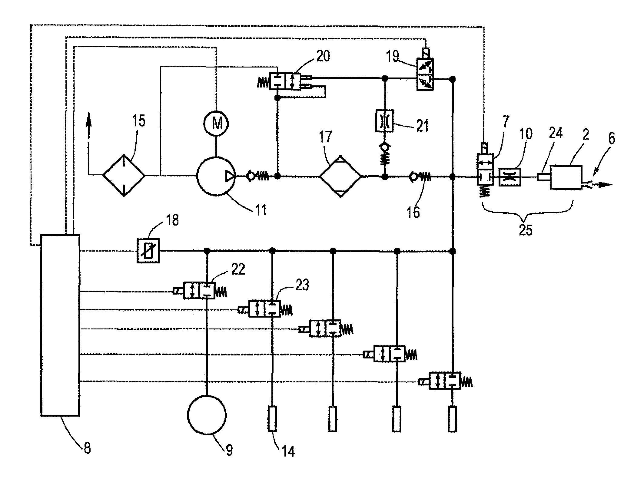
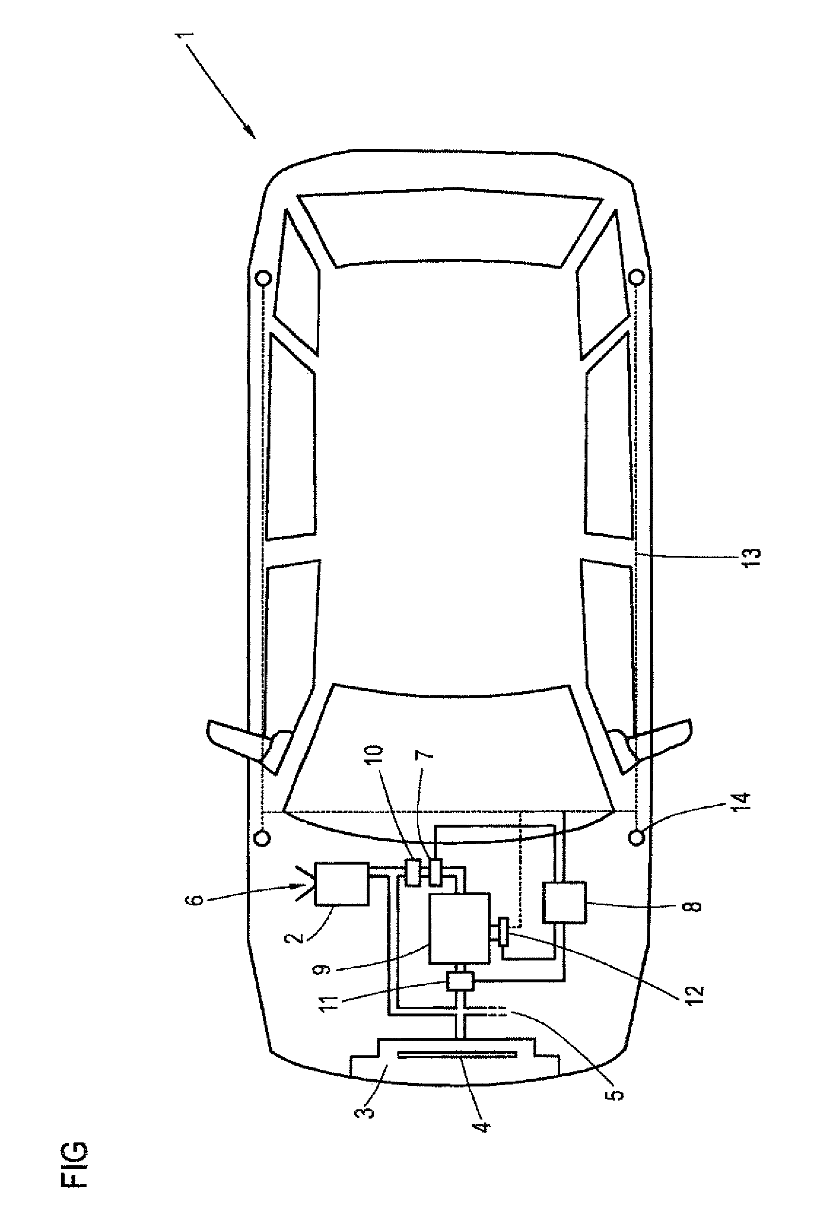
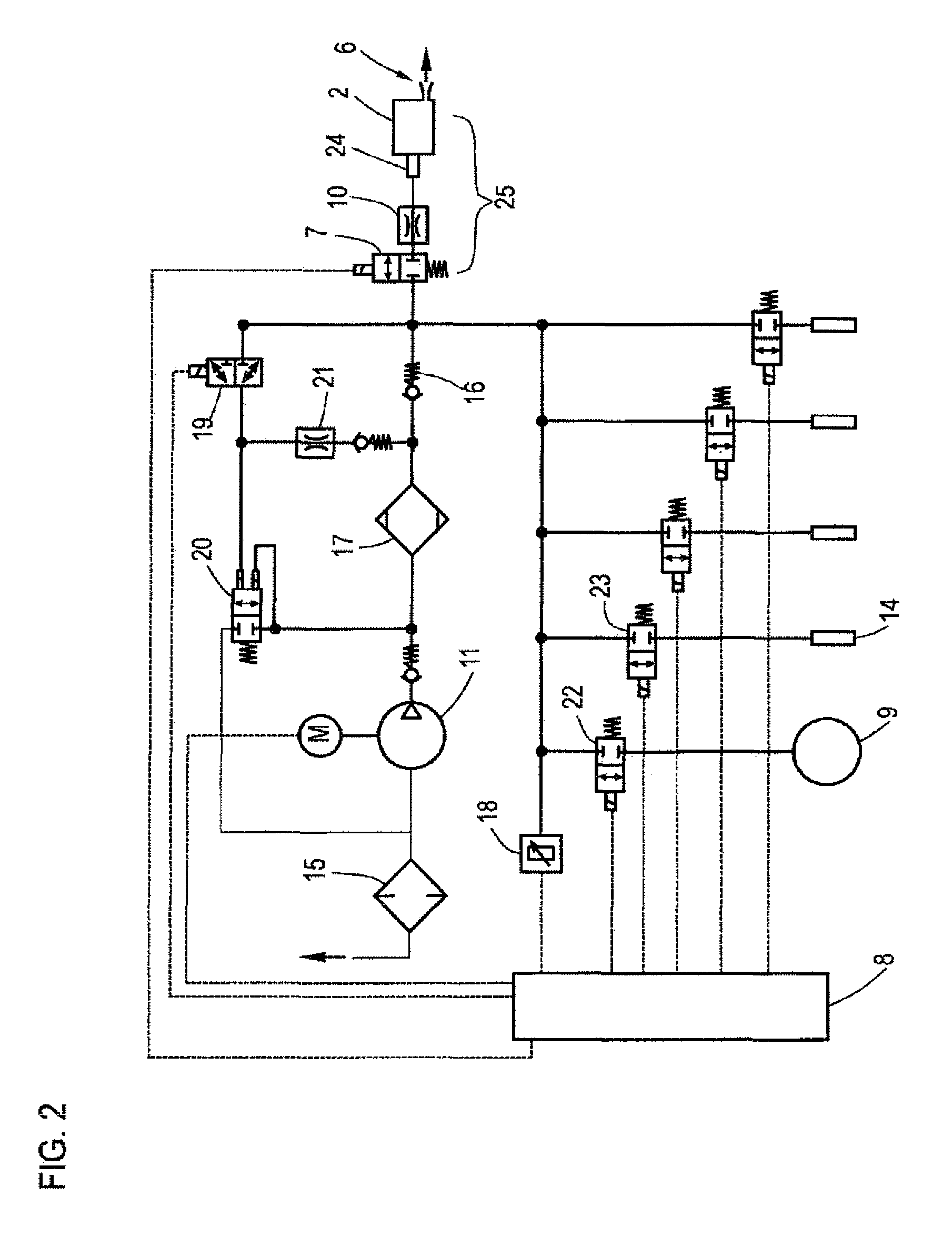
[0028]FIG. 1 shows an exemplary embodiment of a motor vehicle 1 having a cooling system for a battery module 2. The battery module 2 can be cooled with compressed air, in addition to cooling by a conventional ventilation system 3 with a fan 4. In this case, the valve 7 is opened by the control device 8 and compressed air is supplied to the battery module 2 from the pressure accumulator 9. A throttle 10 which limits the flow of gas is also provided between the pressure accumulator 9 and the battery module 2. The gas is thereafter expanded and thus cooled in the subsequent pipe. The gas is supplied to the battery module 2 with overpressure, flows through the battery module 2 and is discharged at the exhaust outlet 6 back into the environment. The pressure accumulator 9 is part of the air suspension system and is connected to the pneumatic circuit 13 of the air suspension system by way of a valve 12. The pneumatic circuit 13 of the air suspension system can supply compressed air specif...


PUM

PropertyMeasurementUnit
volume flow rateaaaaaaaaaa
temperatureaaaaaaaaaa

Abstract

A motor vehicle includes at least one battery module configured to be cooled by compressed gas. The battery module has a cooling system which has an accumulator for compressed gas that can be fed to the battery module for cooling. A control device controls supply of gas from the accumulator to the battery module in dependency of at least one output value from at least one sensor configured to measure a current output from the battery module.

Description

CROSS-REFERENCES TO RELATED APPLICATIONS[0001]This application is the U.S. National Stage of International Application No. PCT / EP20131002420, filed Aug. 13, 2013, which designated the United States and has been published as International Publication No. WO 2014 / 029474 and which claims the priority of German Patent Application, Serial No. 10 2012 016 801.2, filed Aug. 23, 2012, pursuant to 35 U.S.C. 119(a)-(d).BACKGROUND OF THE INVENTION[0002]The invention relates to a motor vehicle with at least a battery module having a cooling system.[0003]Electric mobility is becoming increasingly important in particular from an environmental point. While purely electric vehicles still play a minor role and are particularly suitable for transport in inner cities, hybrid vehicles, especially mild-hybrid vehicles, become increasingly common.[0004]In typical hybrid vehicles, a combustion engine and an electric motor are used. The electric propulsion portion is merely supportive in a mild-hybrid, i.e...

Claims


Application Information

Patent Timeline
Patent Type & Authority Patents(United States)
IPC IPC(8): H01M10/02H01M10/48H01M10/625H01M10/613B60K6/28B60L3/00B60L11/18H01M10/6564B60L11/14B60L50/16
CPCH01M10/6564B60K6/28B60L3/0046B60L11/14B60L11/1874H01M10/48H01M10/613H01M10/625B60L2240/12B60L2240/662H01M10/486H01M2220/20Y02T10/70Y02T10/705Y02T10/7005Y02T10/7077Y02T10/7291Y02T90/16Y10S903/907B60L50/16B60L58/26Y02T10/72Y02T10/7072Y02E60/10
Inventor ACHHAMMER, SIEGFRIEDPOPPEL, ARMINGERLINGER, UWE
Owner AUDI AG
Why Eureka
Try Eureka