
Dental scanner holding apparatus and dental scanner system including the same

a technology of dental scanners and holding apparatuses, which is applied in the field of dental scanner holding apparatus and dental scanner system, can solve the problems of secondary infection, inability to secure perfect sterilization or dryness of dental scanner systems, and inability to secure perfect sterilization or dryness

Active Publication Date: 2018-10-16
VA TECHNOLOGIE +1
View PDF26 Cites 0 Cited by
  • Summary
  • Abstract
  • Description
  • Claims
  • Application Information

AI Technical Summary

Benefits of technology

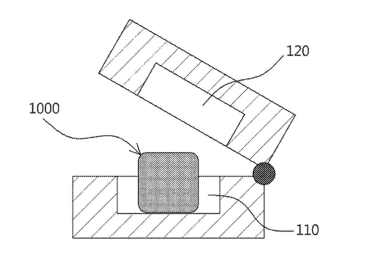
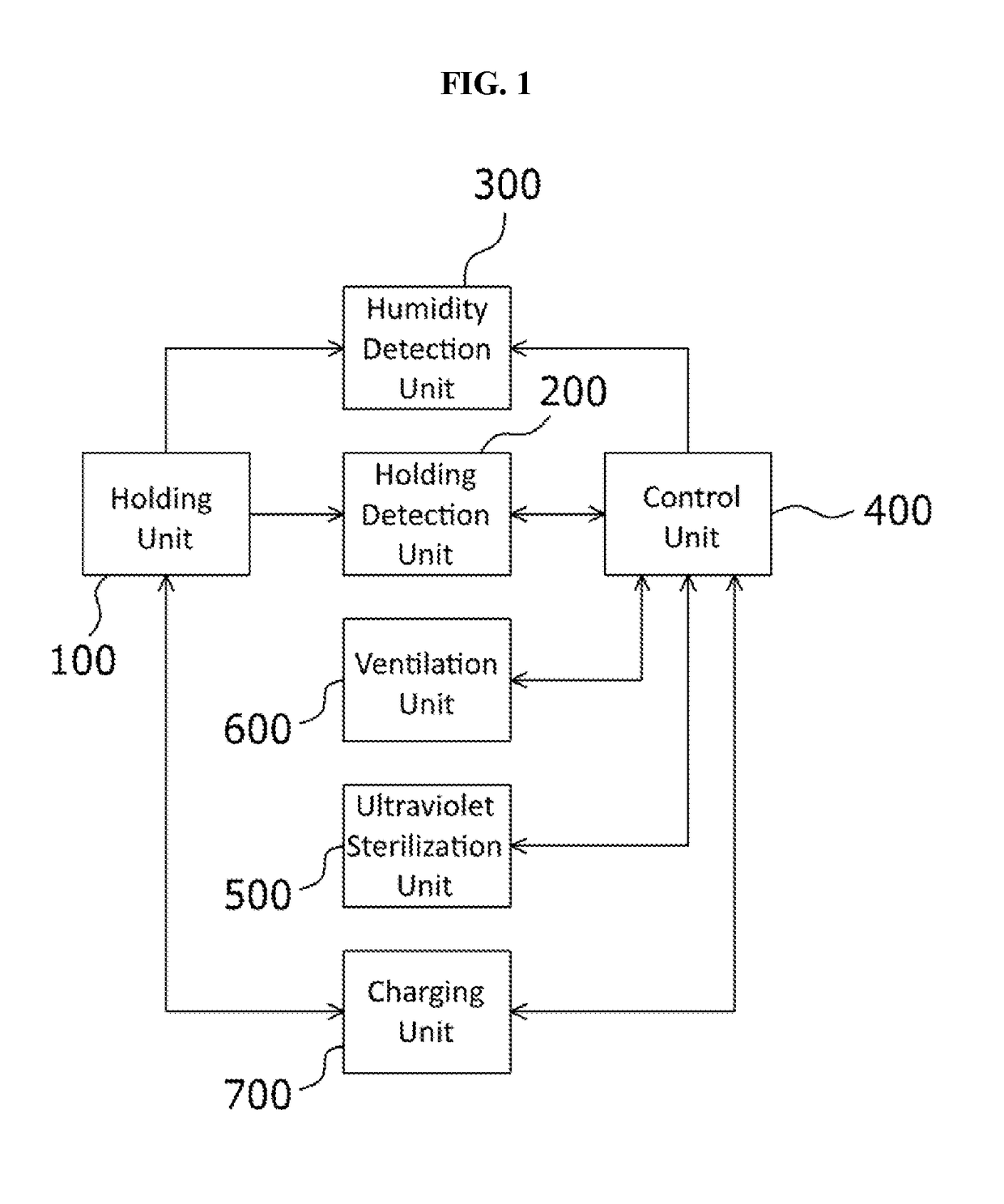
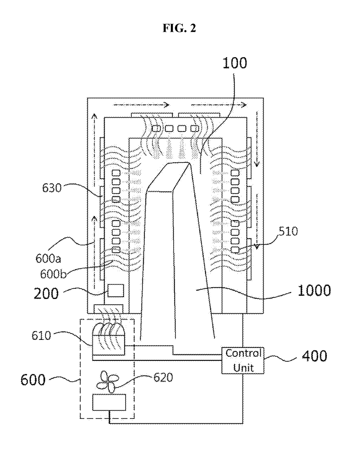
The patent is about a dental scanner holding apparatus that automatically sterilizes and dries a dental scanner using ultraviolet rays and air. The apparatus includes a holding unit that holds the dental scanner, a detection unit that detects if the dental scanner is in the holding unit, a humidity detection unit that detects humidity in the holding unit, and a control unit that generates a sterilization and dehumidification signal based on the detection of the dental scanner and humidity. The ultraviolet sterilization unit then radiates ultraviolet rays into the holding unit to kill bacteria, while the ventilation unit sends air into the holding unit to remove moisture. The dental scanner system includes the holding apparatus, typically in conjunction with a charging unit for the dental scanner, and may also include a water vapor detection unit to alert the control unit of the presence of water vapor. The technical effect of this invention is to provide a convenient and efficient way to ensure the dental scanner is always ready to use, which reduces the risk of cross-contamination and improves overall dental hygiene.

Problems solved by technology

A conventional dental scanner system, such as that described above, may not secure perfect sterilization or dry.
Accordingly, there is a problem in that secondary infection may occur.

Method used


Image

  • Dental scanner holding apparatus and dental scanner system including the same
  • Dental scanner holding apparatus and dental scanner system including the same
  • Dental scanner holding apparatus and dental scanner system including the same

Examples


Embodiment Construction

[0018]Hereinafter, a dental scanner holding apparatus and a dental scanner system including the same will be described in detail with reference to the accompanying drawings through various examples of embodiments.

[0019]However, the embodiments of the present invention may be modified in other various forms and the scope of the present invention is not limited to the following embodiments. In the drawings, the shapes, sizes, etc. of elements may be exaggerated to make the description clear, and elements having the same reference numerals are the same elements.

[0020]The meanings of terms described in this application should be understood as follows.

[0021]Terms, such as the “first” and the “second”, are used to distinguish one element from the other element, and the scope of the disclosed technology should not be restricted by the terms. For example, a first element may be named a second element. Likewise, a second element may be named a first element.

[0022]Furthermore, throughout this...


PUM

PropertyMeasurementUnit
humidityaaaaaaaaaa
transmissionaaaaaaaaaa
heataaaaaaaaaa

Abstract

The present invention relates to a dental scanner holding apparatus and a dental scanner system including the same. The apparatus may include a holding unit configured to have a dental scanner held therein, a holding detection unit configured to detect whether the dental scanner has been held in the holding unit, a humidity detection unit configured to detect humidity within the holding unit, a control unit configured to generate a sterilization signal based on a result of the detection of the holding detection unit regarding whether the dental scanner has been held in the holding unit and to generate a dehumidification signal based on the humidity detected by the humidity detection unit, an ultraviolet sterilization unit configured to radiate ultraviolet rays into the holding unit in response to the sterilization signal, and a ventilation unit configured to send air into the holding unit in response to the dehumidification signal.

Description

CROSS REFERENCE TO RELATED APPLICATIONS[0001]This application is a National Stage Patent Application of PCT International Patent Application No. PCT / KR2015 / 005035 (filed on May 20, 2015) under 35 U.S.C. § 371, which claims priority to Korean Patent Application No. 10-2015-0059602 (filed on Apr. 28, 2015), the teachings of which are incorporated herein in their entireties by reference.BACKGROUND[0002]1. Technical Field[0003]The present disclosure relates to a dental scanner holding apparatus and a dental scanner system including the same, and more particularly, to a dental scanner holding apparatus for automatically sterilizing and dehumidifying the tip of a dental scanner when the dental scanner is held in the dental scanner holding apparatus and a dental scanner system including the same.[0004]2. Related Art[0005]For dental treatment, the teeth of a patient need to be modeled in three-dimensionally accurately and more effectively. To this end, a dental scanner is required. In gener...

Claims


Application Information

Patent Timeline
Patent Type & Authority Patents(United States)
IPC IPC(8): A61C19/00A61C9/00A61C1/00A61L2/24A61L2/10
CPCA61C19/002A61C1/0015A61C9/0053A61L2/24A61L2/10A61L2202/24A61L2202/14A61C19/04
Inventor KIM, YEONG KYUNMOON, AN O
Owner VA TECHNOLOGIE
Learn More