Material reducing device

a technology of reducing device and material, which is applied in the direction of grain treatment, etc., can solve the problems of prior art machines not being able to produce uniformly shaped smaller pieces, known material-reducing machines may not be suitable for use in reducing all types of materials, and may not efficiently reduce fibrous materials. , to achieve the effect of reducing speed, reducing cost and improving efficiency

Active Publication Date: 2018-10-16
ASTEC INDS
View PDF33 Cites 8 Cited by
  • Summary
  • Abstract
  • Description
  • Claims
  • Application Information

AI Technical Summary

Benefits of technology

[0023]The shear blocks may be configured differently in order to accommodate different materials being processed or different operating conditions. For example, the shear blocks may have a beveled leading edge, an angled leading edge or a flat leading edge. The shear blocks may have an outer surface that is interrupted by notches or grooves, or the outer surface may be smooth. In some embodiments of the invention, the shear blocks have a leading surface that comprises a slide angle of greater than 100°, when measured from a horizontal plane that includes the axis of rotation of the rotor assembly. In other embodiments of the invention, the shear blocks have a leading surface that comprises a slip angle that is within the range of 80°-100°, when measured from a horizontal plane that includes the axis of rotation of the rotor assembly. In still other embodiments of the invention, the shear blocks have a leading surface that comprises an anvil angle that is within the range of 50°-80°, when measured from a horizontal plane that includes the axis of rotation of the rotor assembly. In yet other embodiments of the invention, the shear blocks have a leading surface that comprises a catch angle that is within the range of 40°-50°, when measured from a horizontal plane that includes the axis of rotation of the rotor assembly. In still other embodiments of the invention, each of the shear blocks has an outer surface that is curved to describe an arc that is generally parallel to the arc described by the leading edge of the short cutting tool with which it is aligned. In the preferred embodiments of the invention, the shear blocks are mounted on the back plate of the breaker assembly, which allows an operator to maintain a plurality of back plates that can be easily and quickly interchanged, depending on the types of materials being processed.
[0027]Among the advantages of a preferred embodiment of the invention is that it provides a material reducing machine that breaks and reduces materials into uniformly sized pieces. Still another advantage of a preferred embodiment of the invention is that it provides such a machine which operates with greater efficiency than prior art devices. Still another advantage of a preferred embodiment of the invention is that it provides such a machine that can process materials that are incapable of reduction without damaging the machine or stopping its operation. Yet another advantage of a preferred embodiment of the invention is that it provides a material reducing machine that may be readily modified, by changing the breaker assembly, to allow for processing of different types of materials and for operation within a wide range of speeds. Another advantage of a preferred embodiment of the invention is that it allows the material reducing machine to operate effectively at slower speeds, reducing fuel consumption, wear and noise levels. Other advantages and features of this invention will become apparent from an examination of the drawings and the ensuing description.

Problems solved by technology

Known material-reducing machines may not be suitable for use in reducing all types of materials, particularly if there is the possibility that an object which cannot be reduced, such as a large dense metal component or fragment, or a railroad tie that contains metal tie plates and spikes, can be introduced into the machine.
In addition, known material-reducing machines may not efficiently reduce fibrous materials like roofing shingles, because it may require multiple impacts of such materials against the anvil to provide acceptable reduction.
Furthermore, some of the prior art machines may fail to produce uniformly shaped smaller pieces.
Some types of materials tend to break in elongated shapes in the prior art machines, and these elongated shapes may be difficult to handle or transport, and may therefore be generally undesirable.
When these elongated shapes are able to pass through the screen sections of the prior art machines along with more uniformly sized particles, they may contaminate the resulting product with pieces of an undesirable size.
Finally, prior art machines are not readily adaptable to processing different types of materials.

Method used


Image

  • Material reducing device
  • Material reducing device
  • Material reducing device

Examples


first embodiment

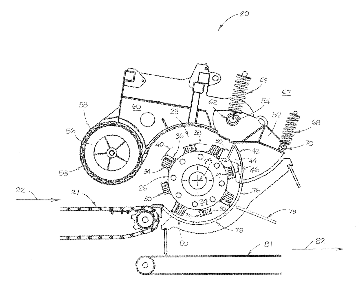
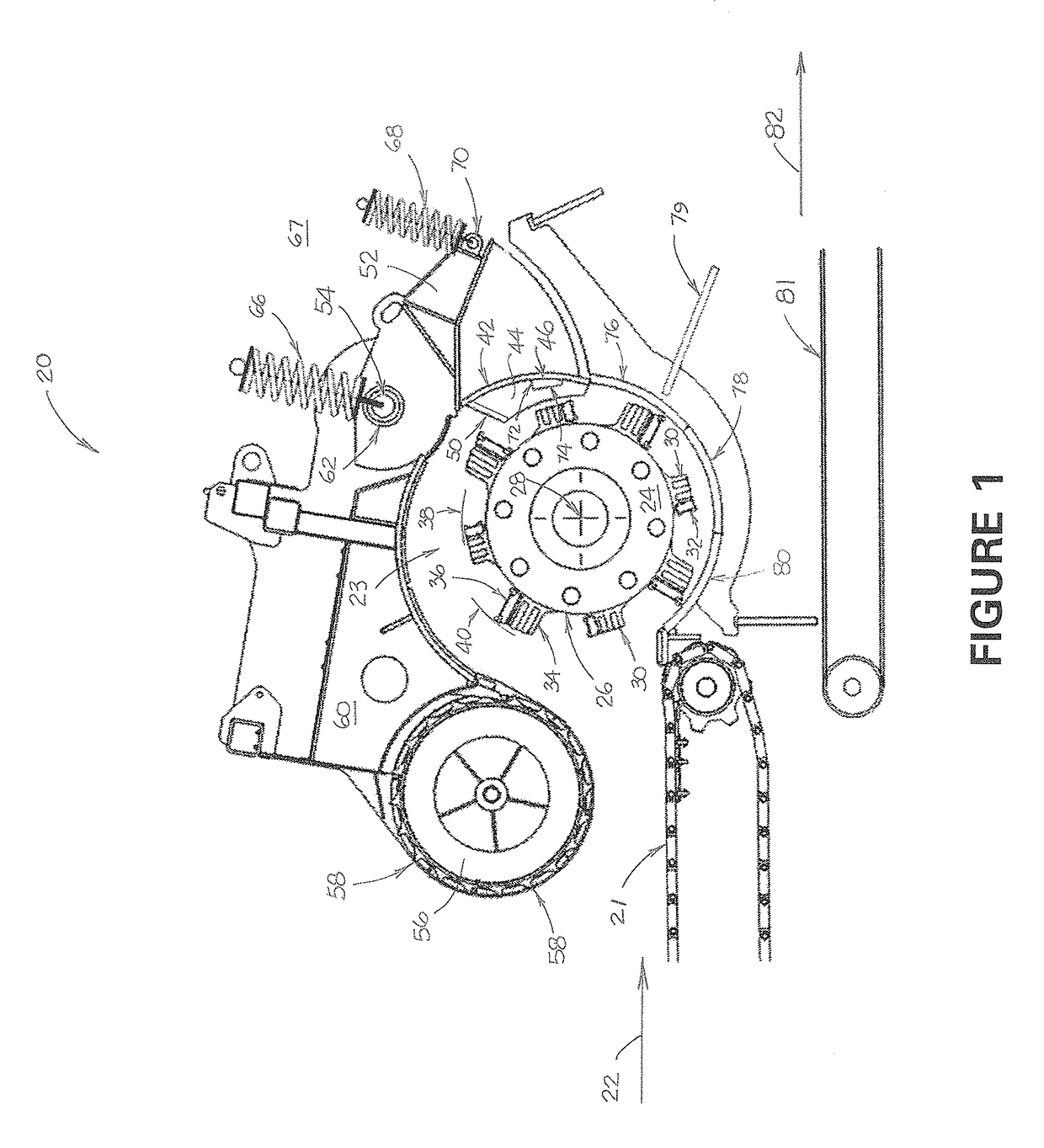
[0051]the invention is illustrated in FIG. 1. As shown therein, material reducing machine 20 includes a generally horizontal material input device such as input conveyor 21. Conveyor 21 is adapted to move material to be reduced in the direction indicated by arrow 22 toward rotor assembly 23. In other embodiments of the invention (not shown in the drawings), the material input device may comprise a chute, and it may be placed with respect to the rotor assembly other than a generally horizontal orientation.

[0052]Rotor assembly 23 comprises a plurality of generally circular rotor plates, one of which, plate 24, is shown in FIG. 1. Because of its generally circular rotor plates, rotor assembly has a generally cylindrical periphery 26. Rotor assembly 23 is adapted to rotate in a clockwise rotational direction, as shown in FIG. 1, about its axis of rotation 28. Rotor assembly 23 comprises a plurality of short cutting tools comprising short tool holders 30 with cutting bits 32 mounted ther...

second embodiment

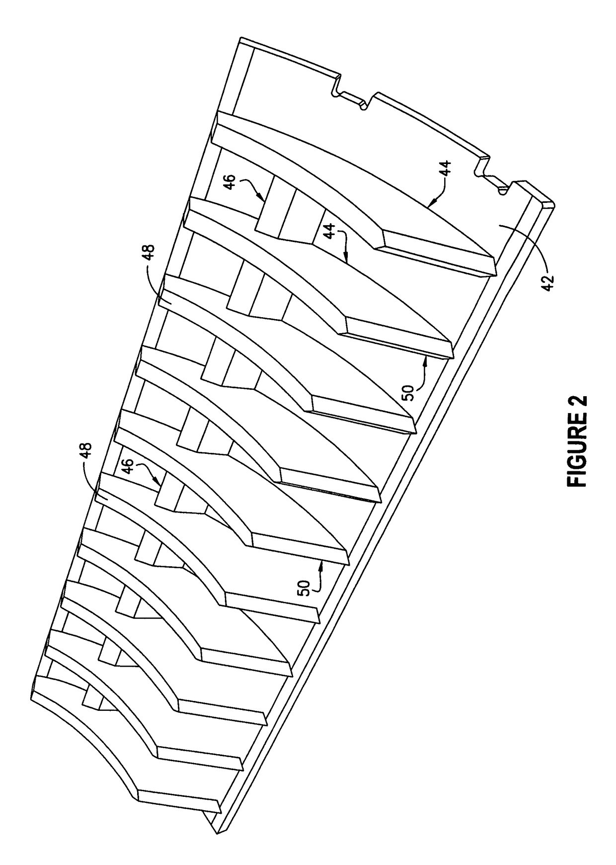
[0054]FIGS. 3 and 4 illustrate the breaker assembly. As shown therein, the breaker assembly includes curved back plate 42 with a plurality of shear blocks 144 and breaker blocks 46 arranged across the width of the machine on the side of back plate 42 that would be adjacent to rotor assembly 23 if this breaker assembly were substituted for the one shown in FIGS. 1 and 2. In that event, shear blocks 144 would extend from back plate 42 towards the rotor assembly a greater distance than breaker blocks 46, and the cutting tools on the rotor assembly and the shear blocks and breaker blocks on the back plate would be arranged so that the long cutting tools would be aligned with breaker blocks 46 and the short cutting tools would be aligned with shear blocks 144. In this embodiment of the invention, the short cutting tools would pass over the curved outer surfaces 148 of shear blocks 144, and the long cutting tools would pass between adjacent shear blocks 144. The leading edges 150 of shear...

third embodiment

[0055]the breaker assembly is illustrated in FIG. 5. As shown therein, the breaker assembly includes curved back plate 42 with a plurality of shear blocks 244 and breaker blocks 46 arranged across the width of the machine on the side of back plate 42 that would be adjacent to rotor assembly 23 if this breaker assembly were substituted for the one shown in FIGS. 1 and 2. In that event, shear blocks 244 would extend from back plate 42 towards the rotor a greater distance than breaker blocks 46, and the cutting tools on the rotor and the shear blocks and breaker blocks on the back plate would be arranged so that the long cutting tools would be aligned with breaker blocks 46 and the short cutting tools would be aligned with shear blocks 244. In this embodiment of the invention, the short cutting tools would pass over the curved outer surfaces 248 of shear blocks 244, which surfaces include a plurality of notches 249. The long cutting tools would pass between adjacent shear blocks 244. A...


PUM


Abstract

A material reducing machine includes a rotor assembly having a plurality of short cutting tools and a plurality of long cutting tools. The short cutting tools are arranged in rows which extend across the length of the rotor assembly, which rows are spaced around the periphery of the rotor assembly. Each of the short cutting tools has a cutting bit with a leading edge that is spaced outwardly from the periphery of the rotor assembly by a short cutter distance. The long cutting tools are also arranged in rows which extend across the length of the rotor assembly, which rows are spaced around the periphery of the rotor assembly. Each of the long cutting tools has a cutting bit with a leading edge that is spaced outwardly from the periphery of the rotor assembly by a long cutter distance that is greater than the short cutter distance of each of the short cutting tools. A breaker assembly includes a plurality of shear blocks, each of which is spaced so as to be aligned with a short cutting tool.

Description

CROSS-REFERENCE TO RELATED APPLICATION[0001]This application is a continuation-in-part of U.S. patent application Ser. No. 13 / 724,063, which was filed on Dec. 21, 2012, and which claims the benefit of U.S. Provisional Patent Application No. 61 / 630,953, filed on Dec. 22, 2011. This application also claims the benefit of U.S. Provisional Patent Application No. 61 / 802,968 which was filed on Mar. 18, 2013.FIELD OF THE INVENTION[0002]The present invention relates generally to machines for use in reducing various materials, especially those obtained in a structural demolition process so that such materials can be more conveniently transported from a demolition site. More particularly, this invention is particularly useful in reducing railroad ties containing or contaminated with metal tie plates and spikes.BACKGROUND OF THE INVENTION[0003]Material reducing machines are well-known for use in connection with the demolition of a house or other structure. Such machines typically include a con...

Claims


Application Information

Patent Timeline
Patent Type & Authority Patents(United States)
IPC IPC(8): B02C13/26B02C18/18B02C18/14B02C18/16B02C23/16
CPCB02C18/18B02C18/145B02C2018/188B02C2018/162B02C2023/165
Inventor PETERSON, ARNOLD NEILBITTROLF, GLENN FORDDEUERLING, BRADLY MICHAEL
Owner ASTEC INDS
Why Eureka
Try Eureka