Quick-release setting tool for an element to be crimped

a technology of setting tool and crimping element, which is applied in the field of quick release setting tool, can solve problems such as not being perfectly orthogonal, and achieve the effect of convenient and quick interchang

Active Publication Date: 2022-02-01
BOLLHOFF OTALU SA
View PDF3 Cites 0 Cited by
  • Summary
  • Abstract
  • Description
  • Claims
  • Application Information

AI Technical Summary

Benefits of technology

[0008]One object of the invention is to provide an setting tool comprising a placing nose provided with a pull rod that is able to be easily and quickly interchanged and which exerts perfectly symmetrical forces when crimping of the crimp part is performed.
[0026]to prevent the pull rod from being separated from the drive shaft by sliding by means of a force perpendicular to the axis of rotation when the first and second imprints are mechanically coupled.
[0036]It is advantageous to provide for the method to comprise a first step of translation of the drive shaft along the axis of rotation of the drive shaft to reduce the space occupation of the drive shaft along the axis of rotation and to place the pull rod on the axis of rotation.

Problems solved by technology

This can give rise to asymmetric forces when crimping of the nut is performed, and the latter may not be perfectly orthogonal to the plate to which it is fixed.

Method used


Image

  • Quick-release setting tool for an element to be crimped
  • Quick-release setting tool for an element to be crimped
  • Quick-release setting tool for an element to be crimped

Examples


Embodiment Construction

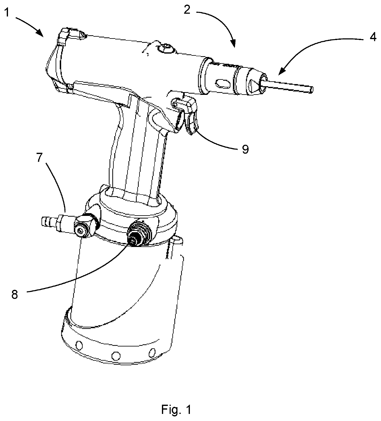
[0046]An setting tool for placing a crimp part such as the one represented in the figures is provided with a body 1, a placing nose 2 able to be formed by one or more parts being fixed thereon.

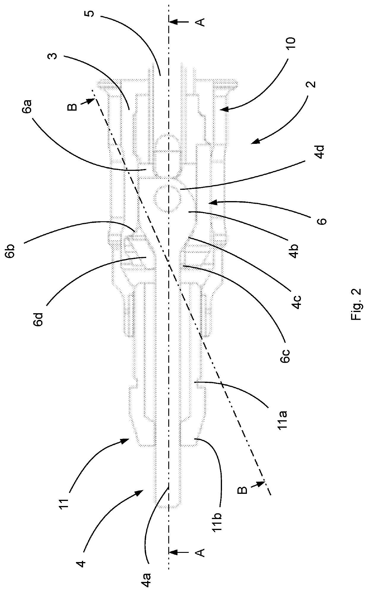
[0047]The placing nose 2 defines an open chamber 3 which opens out at its two opposite ends to allow a pull rod 4 to pass through. The placing nose 2 has a front end, which is the end located on the working area side, and a rear end located on the opposite side from the working area. Both ends of the placing nose 2 are provided with an opening connected to the chamber 3 to allow the pull rod 4 to pass when assembly or disassembly of the latter is performed.

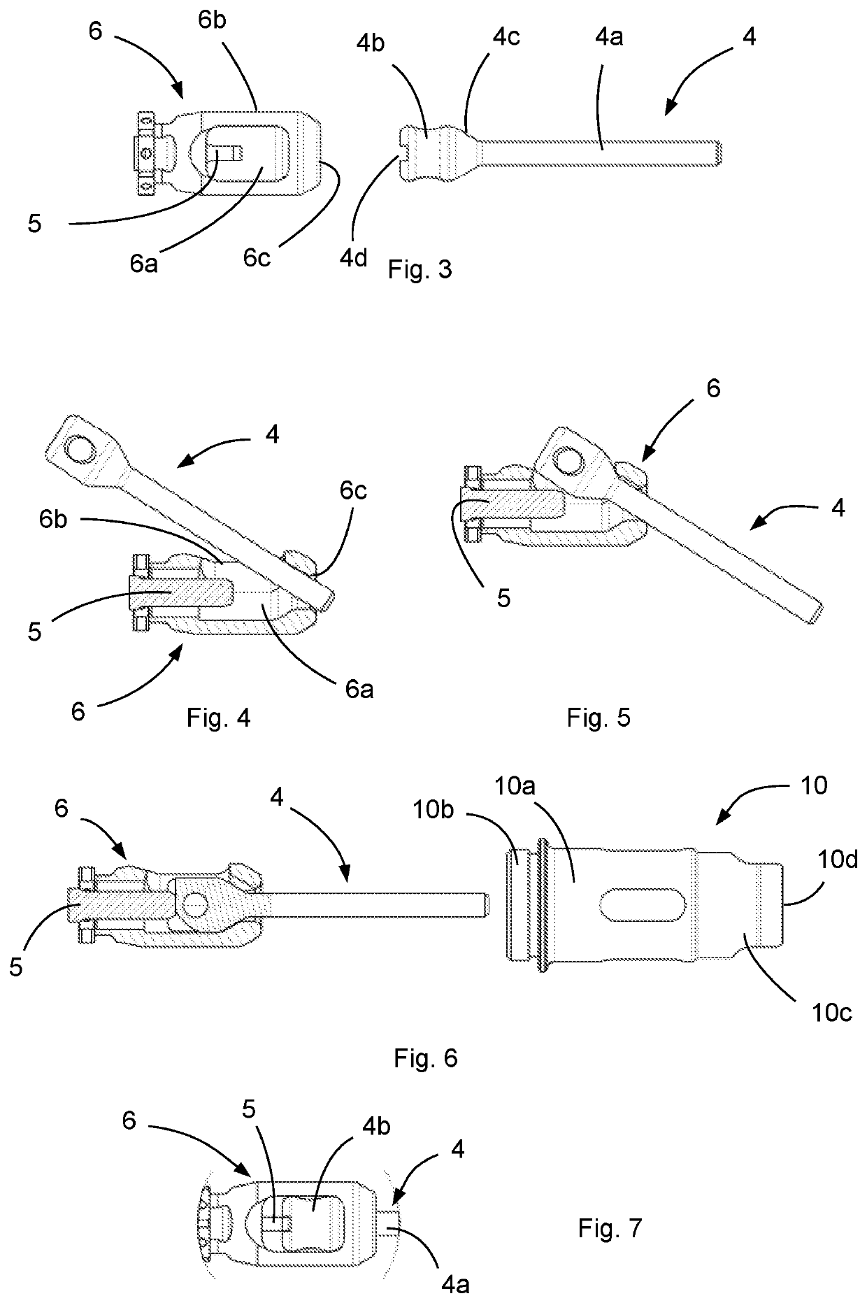
[0048]The pull rod 4 is configured to be mechanically coupled with the crimp part. In this way, the movements made and the forces applied by the pull rod 4 are transferred to the crimp part.

[0049]Advantageously, the pull rod 4 is configured to be screwed into or around the crimp part and to then be unscrewed when crimping is performed. For t...


PUM


Abstract

A setting tool includes: a body with at least a drive shaft connected to a pull rod designed to be screwed onto the crimp part, to drive the pull rod in rotation along an axis; a draw sleeve fixed to the body and connected to the pull rod, to translate the pull rod along the axis; and a placing nose, to house the pull rod rear end, the drive shaft front end, and the draw sleeve. The draw sleeve front end includes a cavity opening onto a first through hole on the side wall, and a second hole on the drive shaft axis of rotation, the through holes allow the pull rod front end to pass through the holes, to allow the pull rod rear end to pass through the first through hole, and to enable the pull rod to be placed along the drive shaft axis of rotation.

Description

FIELD OF THE INVENTION[0001]The invention relates to a setting tool for fitting a crimp part, equipped with a quick-release pull rod. The invention also relates to the method for assembling the setting tool.STATE OF THE ART[0002]The use of crimp parts is commonplace in industry, and in particular in the automobile, aeronautic or naval construction fields. A large variety of crimp parts such as clinch nuts are used.[0003]Crimping of parts is generally performed by means of portable setting tools using an oleo-pneumatic, electric or other form of power. This type of setting tool is equipped with a pull rod designed to be screwed into or around the crimp part. The tool is also provided with a system for driving in rotation and a pulling system for performing screw-tightening and crimping of the crimp part.[0004]More precisely, to crimp a part such as a nut on a plate, the body of the nut is first inserted through a hole of the plate. The pull rod of the tool, advantageously comprising ...

Claims


Application Information

Patent Timeline
Patent Type & Authority Patents(United States)
IPC IPC(8): B25B27/00B25B23/00
CPCB25B27/0014B25B23/0007B25B27/14
Inventor MACCHIERALDO, DAVID
Owner BOLLHOFF OTALU SA
Why Eureka
Try Eureka