Microscope stage apparatus and movement means

a technology of microscopy and stage equipment, applied in the field of bidirectional, ergonomic stage movement means, can solve the problems of difficulty in using with higher power objectives, frustration during microscopist attempts to relocate, and difficulty in product manufacturing, so as to achieve easy and quick interchange, control, precise and rapid movement

Inactive Publication Date: 2005-05-26
LEICA MICROSYSTEMS CMS GMBH
View PDF9 Cites 5 Cited by
  • Summary
  • Abstract
  • Description
  • Claims
  • Application Information

AI Technical Summary

Benefits of technology

[0014] A general object of the invention is to provide a stage assembly movement means for movement of a microscope specimen that can be easily and quickly interchanged for use by right-handed and left-handed people.
[0015] Another object of the invention is to provide an ergonomic stage movement means which allows controlled, precise and rapid movement of the stage assembly in an X and Y direction.

Problems solved by technology

This plain stage is very useful for quick examination of specimens, but is very difficult to use with higher power objectives (above 20×).
At high magnification, small translations of the specimen slide will quickly translate features of interest completely out of the viewing field, leading to frustration during microscopist attempts to relocate them.
However, due to the variety of microscopists using these instruments, both left and right-handed stages are required.
Having to match the stage configuration to the microscopist's predominate hand creates difficulty during manufacture of products.
After the assembly is complete, changing the configuration requires significant disassembly and reassembly time, as well as requiring a complete additional stage mechanism.
This problem also requires microscope manufacturers to maintain inventories of both left-handed and right-handed stage assemblies.
While conventional microscope design has not necessarily been a problem for short-term use, long-term sessions have historically created problems for microscopists.
Prolonged use of a microscope may lead to physical (sometimes permanently debilitating) problems especially with the visual and musculoskeletal systems.

Method used


Image

  • Microscope stage apparatus and movement means
  • Microscope stage apparatus and movement means
  • Microscope stage apparatus and movement means

Examples


Embodiment Construction

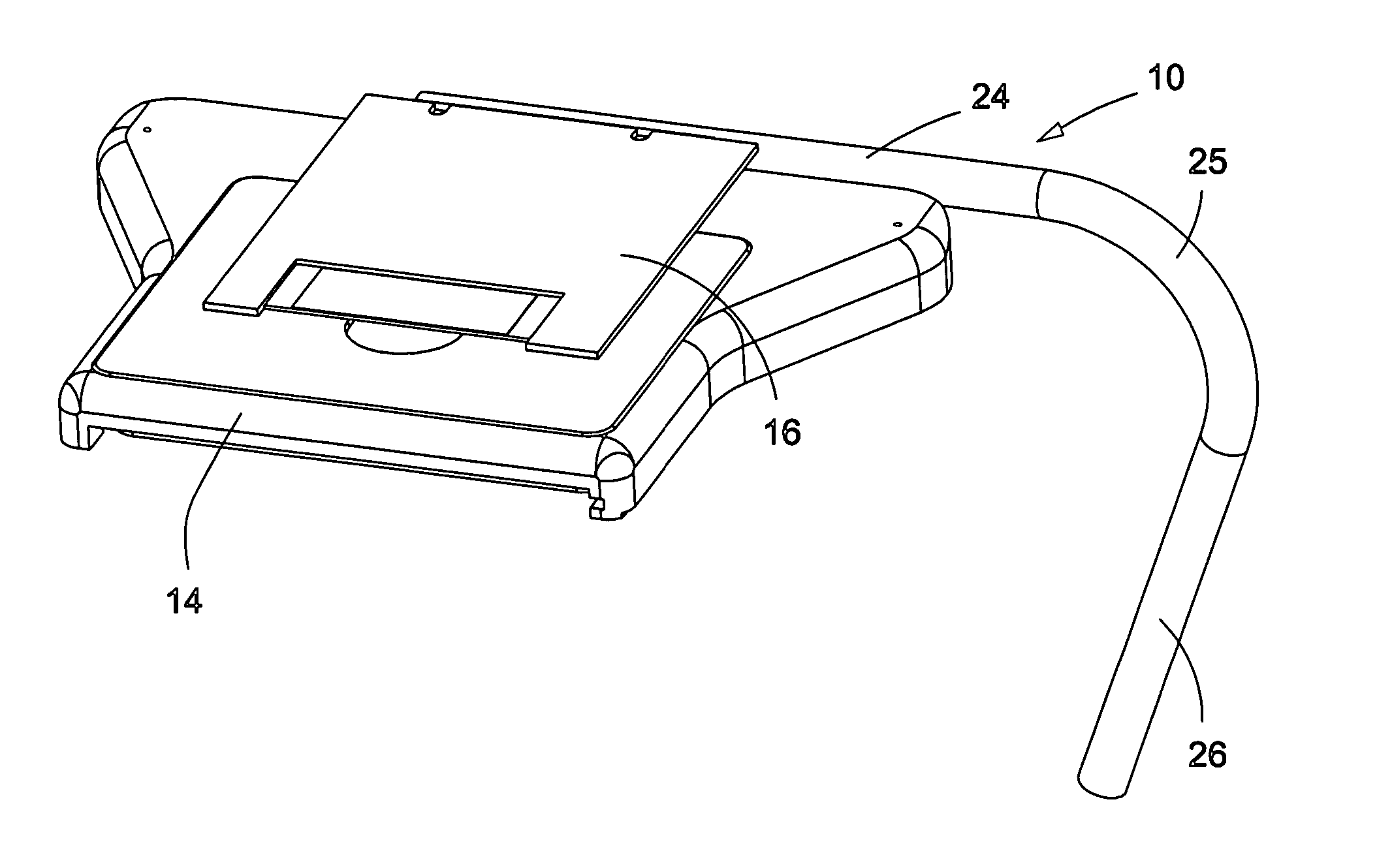
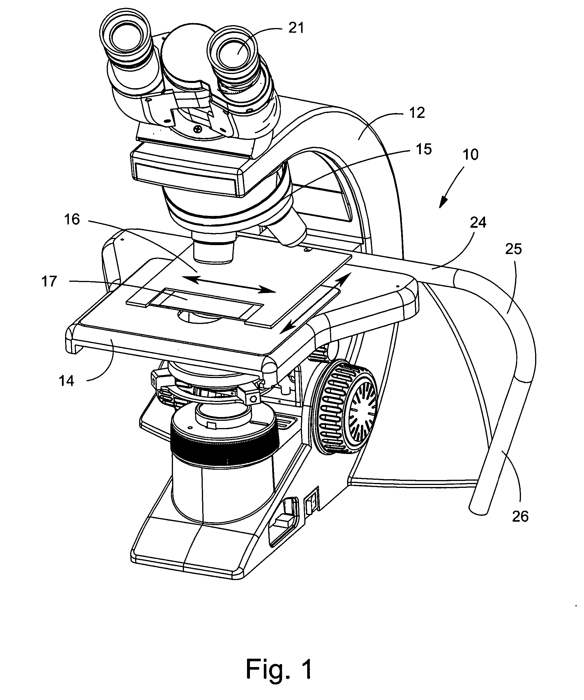
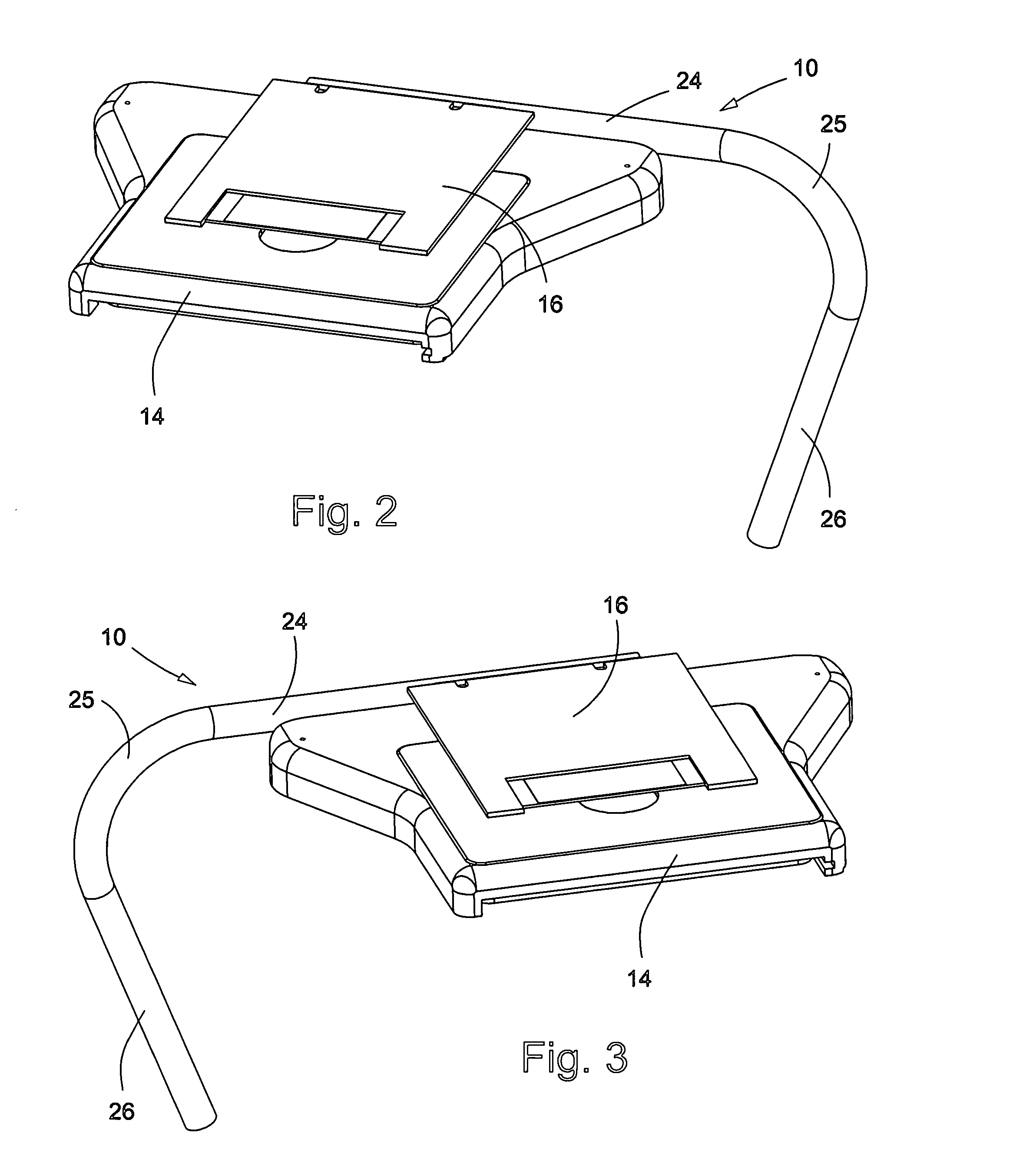
[0025] At the outset, it should be appreciated that like drawing numbers on different drawing views identify identical structural elements of the invention. While the present invention is described with respect to what is presently considered to be the preferred embodiments, it is understood that the invention is not limited to the disclosed embodiments.

[0026] Furthermore, it is to be understood that this invention is not limited to the particular methodology, materials and modifications described and as such may, of course, vary. It is also to be understood that the terminology used herein is for the purpose of describing particular embodiments only, and is not intended to limit the scope of the present invention, which will be limited only by the appended claims.

[0027] Unless defined otherwise, all technical and scientific terms used herein have the same meaning as commonly understood to one of ordinary skill in the art to which this invention belongs. Although any methods, devi...


PUM


Abstract

An apparatus for controlling a microscope stage assembly including a bidirectional, ergonomic stage movement means operatively arranged to be detachably secured to the microscope stage assembly. A microscope stage movement means including at least one substantially circular stick with an attachment end and a gripping end wherein said attachment end is operatively arranged to be detachably secured to a microscope stage assembly. An interchangeable microscope stage movement device for providing X and Y movement of a sample which includes a microscope stage assembly and a joystick detachably secured to the stage assembly at more than one location of the stage assembly.

Description

FIELD OF THE INVENTION [0001] The present invention relates generally to a microscope stage apparatus, and more particularly, to a bidirectional, ergonomic stage movement means. BACKGROUND OF THE INVENTION [0002] A standard microscope includes a light source, an objective lens and viewing arrangements (e.g. eyepiece or camera / CRT) for examination or manipulation of objects at high magnifications. Standard microscopes include commercially available petrographic, metallographic and semiconductor microscopes. [0003] Microscopes are designed to include a stage where the specimen (usually mounted onto a glass slide) is placed for observation. A stage can be classified according to design and functionality. In the simplest case, the plain stage assembly consists of a rectangular or square design containing several clips to hold the specimen slide. The stage assembly also contains an opening in the center to allow light from the condenser to pass through the specimen (the stage opening). [...

Claims


Application Information

Patent Timeline
Patent Type & Authority Applications(United States)
IPC IPC(8): G02B21/24G02B21/26
CPCG02B21/26G02B21/242
Inventor BONAVENTURA, RUSSELLPARKS, SCOTT W.
Owner LEICA MICROSYSTEMS CMS GMBH
Why Eureka
Try Eureka