
Cycling glove and support area pads

a technology for supporting pads and gloves, applied in the field of support surfaces, can solve the problems of numb hands and fingers of riders, easy compression of the supporting parts, and a lack of suppor

Active Publication Date: 2018-10-23
DASSLER ALFRED K +2
View PDF30 Cites 2 Cited by
  • Summary
  • Abstract
  • Description
  • Claims
  • Application Information

AI Technical Summary

Benefits of technology

The invention is about providing comfortable cycling gloves with a padded support element for the palm. The padded glove has a cavity for inserting a human hand, with a palm wall for covering the palm. The support element consists of a plurality of interconnected spherical shaped structures that flexibly bend to provide a comfortable fit and prevent fatigue of the palm. The glove can be used for activities such as weight lifting or in cycling where heavy loads are supported by the hands. It is flexible and comfortable to wear with any orientation relative to the handlebars. Overall, the technical effect of the invention is to provide a well-padded and comfortable glove for cycling and other activities.

Problems solved by technology

The disadvantages of existing padding in cycling gloves is that the cushion members are constructed to be very soft (in the range of hardness on the Shore OO scale) and become easily compressed between the user's hands and the handlebars of the bicycle.
The cushion offers no support and thus often causes numbness in the hands and fingers of the rider and over time possible nerve damage to the rider's hands.
Numbness may typically be caused by the pressure generated on the hand by the handle bars while riding.
Additionally, the handlebars compress and deform the padding because of the small contact area of the handlebar on the glove.
This further deteriorates the ability of the glove to protect the hand from the handlebars.
However, the use of cushioning on the bar or glove is not a successful solution, as evidenced by the high number of riders that experience continued numbness / tingling in the hands and or fingers during and after riding.
Accordingly, a long-standing problem for cyclists is the problem of numbness / tingling in the hands and fingers when riding for extended periods of time.

Method used


Image

  • Cycling glove and support area pads
  • Cycling glove and support area pads
  • Cycling glove and support area pads

Examples


Embodiment Construction

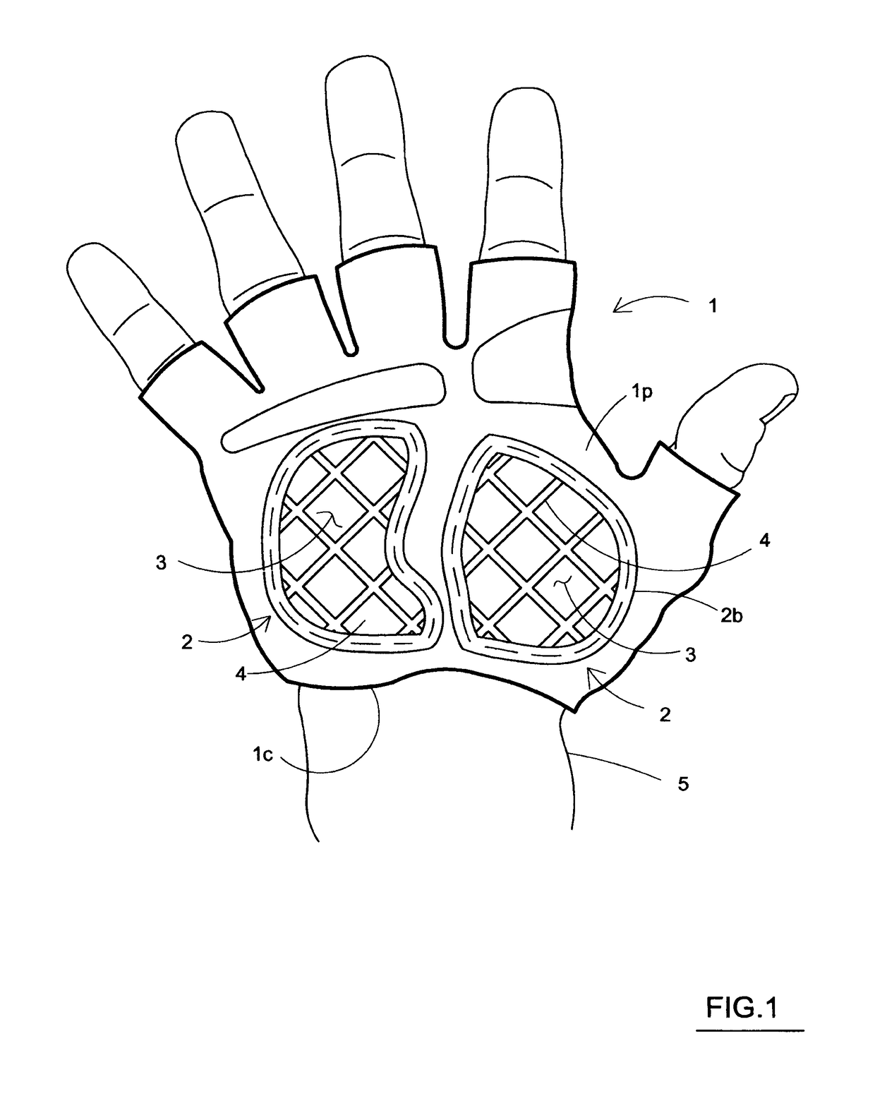
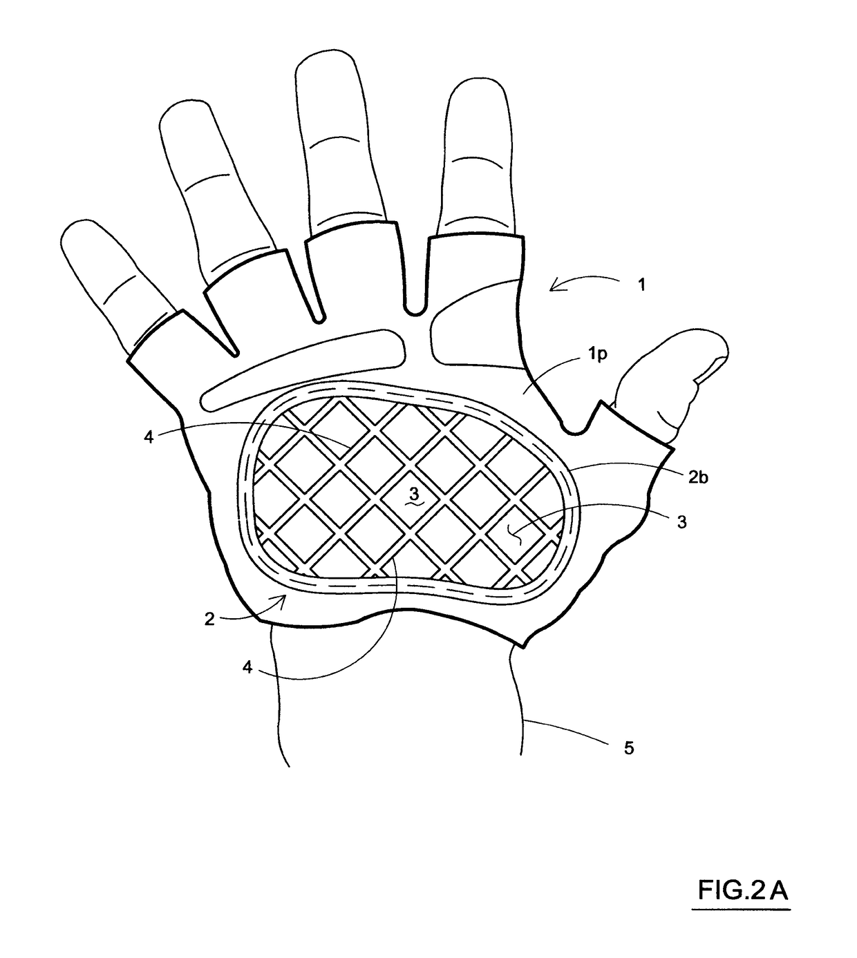
[0074]Referring now to the figures of the drawing in detail and first, particularly, to FIGS. 1 and 2 thereof, there is seen a glove / glove body 1 according to the invention. The glove 1 includes support regions 2 which are defined by a plurality of rigid plate elements 3 that are interconnected by a hinge 4 such as a living hinge. The support region(s) 2 are disposed at a palm area / portion 1p of the glove 1, which corresponds to a palm of a user's hands. The palm area 1p may have a circumferential border 2b. The glove 1 includes a cavity 1c for receiving a user's hand H. The cavity is at least partially defined by a palm wall 1w. The rigid plate elements 3 may be formed of plastic having a durometer of between 50 and 150 on the Rockwell R scale, which includes materials such as polypropylene, nylon, and polystyrenes etc. The use of the hinge 4 permits the support region 2 to flex, which prevents the support region 2 from pulling on other parts or areas of the glove 1 such as the are...


PUM


Abstract

A support element including a padding structure constructed of a plurality of interconnected spherical shaped structures together defining a pliable support element. The spherical shaped structures are interconnected to one another with a connection defining flexible interconnectors for enabling the padding structure to be flexibly bent.

Description

CROSS-REFERENCE TO RELATED APPLICATIONS[0001]This application claims the benefit of U.S. Provisional Application Ser. No. 61 / 241,063, filed on Sep. 10, 2009, entitled Cycling Glove, U.S. Provisional Application Ser. No. 61 / 325,481, filed on Apr. 19, 2010, entitled Cycling Glove, U.S. Provisional Application Ser. No. 61 / 388,137, filed on Sep. 30, 2010, entitled Pressure Location Pad and Non-Provisional U.S. patent application Ser. No. 12 / 879,183, filed Sep. 10, 2010, published Mar. 10, 2011 as Pub. No.: US 2011 / 0055995 A1 entitled Cycling Glove Support Area, these prior applications are incorporated herein by reference in their entirety.BACKGROUND OF THE INVENTION[0002]Field of the Invention[0003]The invention relates to a support surface for articles which contact body parts, more specifically, for padding in articles such as cycling gloves, gloves, shoes, insoles, socks, seats, protective pads and padding and the like.[0004]Description of the Related Art[0005]Existing cycling glove...

Claims


Application Information

Patent Timeline
Patent Type & Authority Patents(United States)
IPC IPC(8): A41D19/00A41D19/015A63B71/12A63B71/14
CPCA41D19/01523A63B71/1225A63B71/141Y10T428/249921Y10T428/24479Y10T428/24752A63B2071/125
Inventor DASSLER, ALFRED K.SCHWARTZ, ROBERT M.HOFELDT, ALBERT J.
Owner DASSLER ALFRED K
Learn More