
Stent-graft

a stent and graft technology, applied in the field of stent grafts, can solve the problems of poor adhesive properties, difficult to get the stent-graft to flexibly follow the movement of the blood vessel, and follow the shape of the curve-shaped blood vessel, so as to prevent blood leakage into the gap, improve the adhesion, and reduce the rigidity

Active Publication Date: 2020-06-30
PTMC INST
View PDF30 Cites 0 Cited by
  • Summary
  • Abstract
  • Description
  • Claims
  • Application Information

AI Technical Summary

Benefits of technology

This invention relates to a stent-graft that can be used to repair damaged blood vessels. The invention includes an auxiliary elastic wire that keeps the stent-graft secure in place and prevents it from tilting or moving. The auxiliary elastic wire is also flexible, allowing it to conform to the natural curvatures of the blood vessel without causing blood leakage or unexpected movement. This makes the stent-graft suitable for long-term use without causing any complications. Additionally, the invention enables the elastic ring to be folded and easily stored in a small delivery sheath, making the stent-graft easier to handle and transport.

Problems solved by technology

However, when using a ‘stiff’ stent-graft, it can be difficult to get the stent-graft to flexibly follow the movement of the blood vessel, or to follow the form of a curve-shaped blood vessel.
These shortcomings can lead to poor adhesive properties between the stent-graft and the blood vessel that may result in blood entering gaps between the stent-graft and the inner wall of the blood vessel.
In addition, in the case of the ‘z type’ stent-graft there is a chance for a pointed part to form in a bent stent that might break or otherwise damage the blood vessel.
A practical problem that arises with the use of ‘hybrid type’ stent-grafts, as the ones described in patent documents 4 and 5, is that due to their structure, it is questionable whether or not these stent-grafts can in fact be transported with conventional unobtrusive methods to an affected target area.
Folding a ‘hybrid-type’ stent-graft, such as the ones described in patent documents 4 and 5, in a radial direction for the purpose of housing it in a delivery sheath can pose a challenge.
This is because when the ‘z-type’ end-parts, and ‘helical-type’ middle parts are made to shrink in the radial direction, they fold in a substantially different manner, which leads to conflicting forces that resist one another along the body of the hybrid stent-graft, and particularly at the sections of the stent graft where the ‘z-type’ parts and ‘helical-type’ part meet.
As a result, with consideration of the conflicting forces described above, it can be expected that folding the ‘hybrid-type’ stent-grafts described in documents 4 and 5 will be extremely difficult in reality.
Some degree of folding and shrinking of the stent-graft in the radial direction is likely possible with the exertion of force, but even under severe pressure, the diameter of the folded hybrid stent-graft would likely be too large to be housed in a delivery sheath for delivering the stent-graft to an affected target area.

Method used


Image

  • Stent-graft
  • Stent-graft
  • Stent-graft

Examples


first embodiment

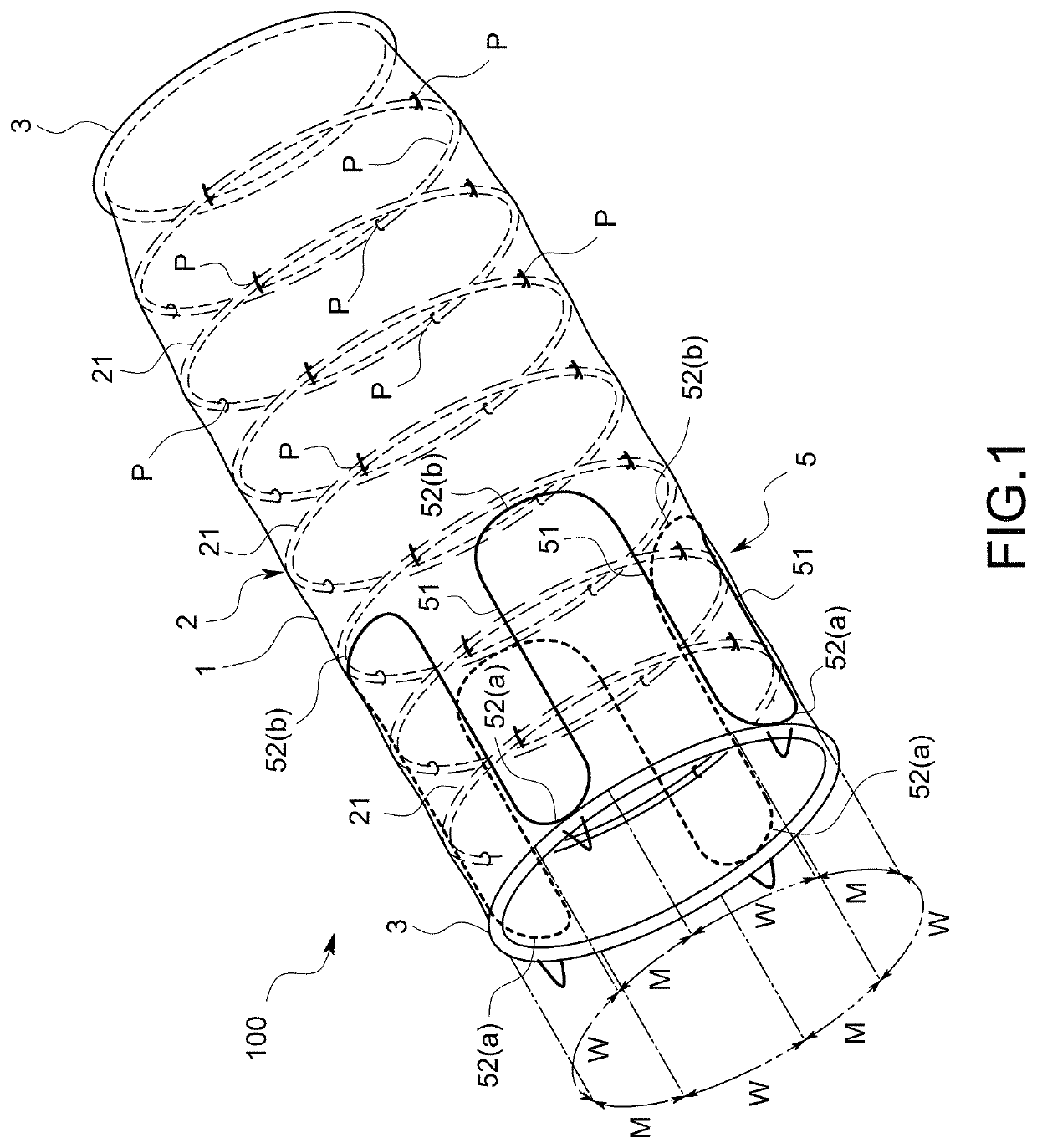
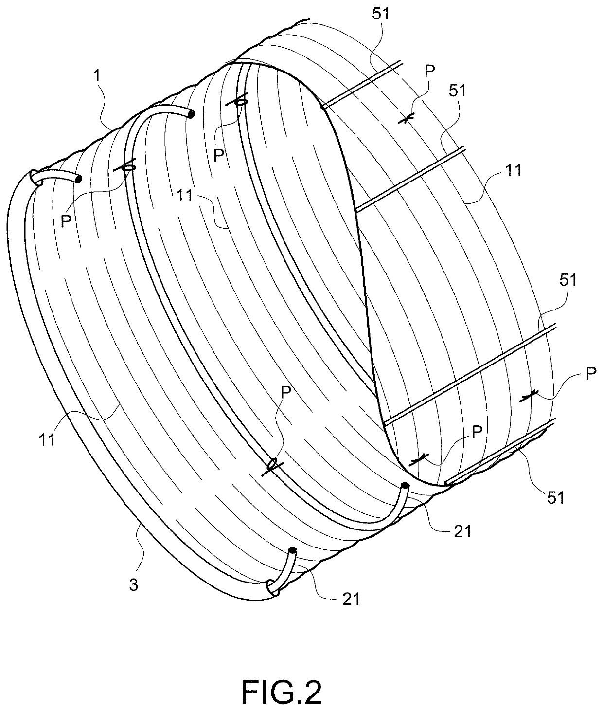
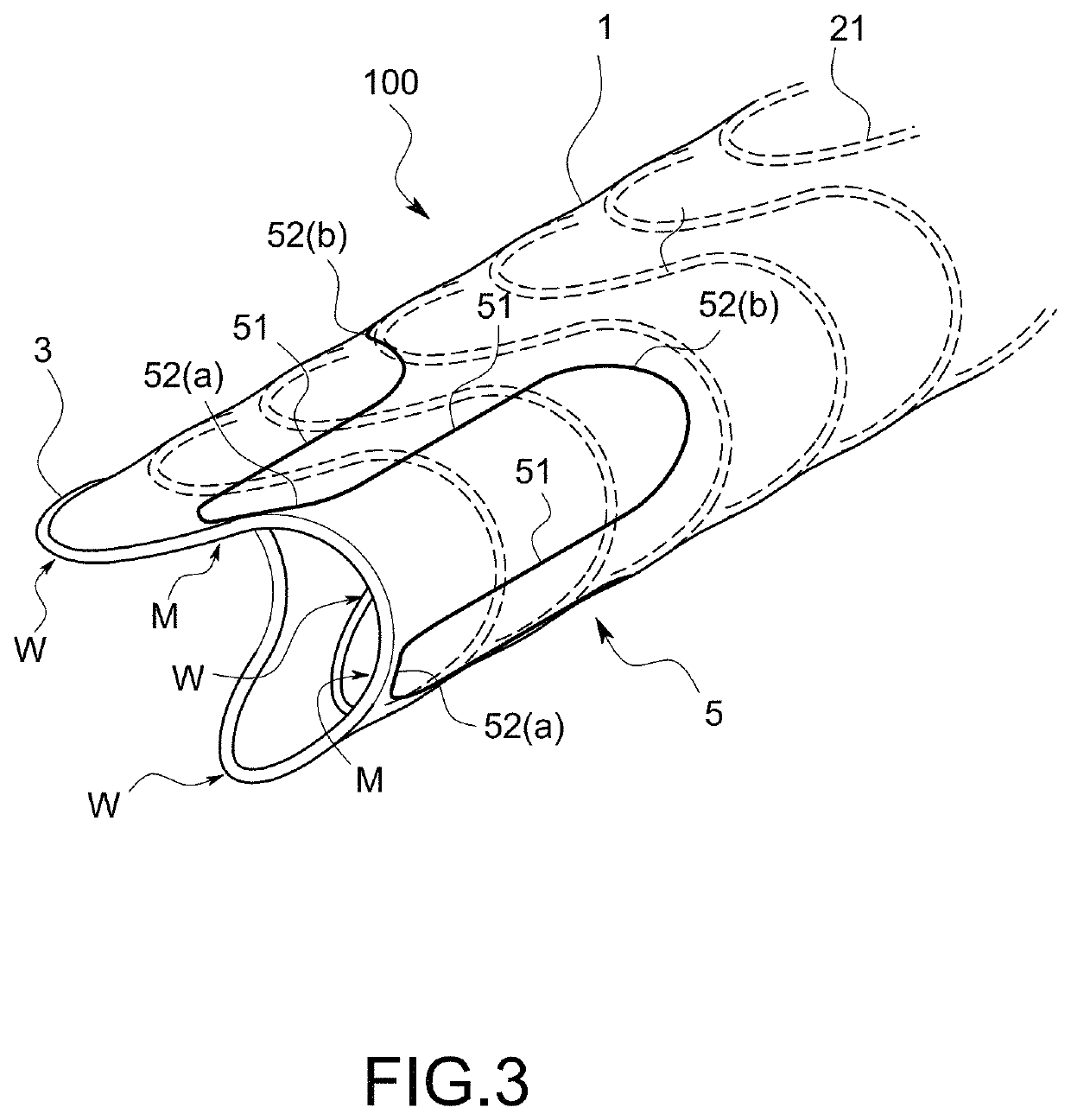
[0059]A stent-graft 100 in accordance with this embodiment comprises a graft 1 (an artificial blood vessel) of a tubular shape whose ends are both open, and a stent 2 mounted on the graft 1 in order to keep the shape of the graft 1 as shown in FIG. 1 and FIG. 2. The stent-graft 100 is transported to and released inside a blood vessel having a lesion portion, such as a thoracic aorta aneurysm or an abdominal aorta aneurysm, via a catheter 200 (shown in FIG. 6 through FIG. 8). Then the stent-graft 100 sticks to an inner wall of a blood vessel due to its own tendency to expand in a radial direction and due to the force exerted by blood pressure in the blood vessel. The stent-graft 100 then functions as an artificial blood vessel by covering the blood vessel walls from the inside.

[0060]The graft 1 is formed into a tubular shape made of a resin sheet that is durable and has little likelihood of reacting with living tissue. As shown in the partial break view of FIG. 2, the graft 1 is conf...

second embodiment

[0121]Next, a second embodiment of this invention will be explained.

[0122]A stent-graft 100 in accordance with this embodiment is arranged to cover the inside the walls of a (distal) aortic arch aneurysm (A).

[0123]A concrete explanation will follow.

[0124]The stent-graft 100 comprises, as shown in FIG. 13, a main tube 101 that is mounted on an aortic arch portion and covers from the inside the walls of an aortic aneurysm (A), and a diverging tube 102 that diverges from one end-part located in the upstream side of the main tube 101, and that is inserted into a left subclavian artery (B1).

[0125]A basic configuration of the main tube 101 is the same as that of the stent-graft, having a single tube, in the first embodiment. More specifically, the main tube 101 comprises a first graft (1A), multiple elastic rings (21A) mounted on the first graft (1A), and auxiliary elastic wires 5, of which one is arranged at the upstream side opening, and the other at the downstream side opening of the f...


PUM


Abstract

This invention provides a stent-graft that has both shape-maintainability and flexibility, and when implanted in a living body, the stent-graft performs its intended functions for a considerably long period of time relative to conventional stent-grafts, without causing conflict. The stent-graft comprises a stent comprising multiple elastic rings and a graft. An auxiliary elastic wire whose rigidity is lower than that of the stent is arranged at the end-part of the graft, and the auxiliary elastic wire is connected to the multiple elastic rings at the opening part.

Description

FIELD OF THE ART[0001]This invention relates to a stent-graft intended for implantation in a living body.BACKGROUND ART[0002]For a stent-graft implanted inside of a blood vessel such as an artery, a certain degree of shape-maintainability, also referred to as ‘rigidity’ or ‘stiffness,’ is required in order to avoid contingent transformations of the stent-graft, such as excessive dents or bending, owing to a movement of the blood vessel or a change of blood flow / blood pressure after the stent-graft has been implanted in the blood vessel. At the same time, a degree of ‘flexibility’ is also required in order for a stent-graft to be able to tightly attach to an inner wall of the blood vessel, and to follow a possible movement from expansion or shrinkage of the blood vessel.[0003]Stent-grafts that place emphasis on shape-maintainability are known as ‘stiff’ stent-grafts. One example of a ‘stiff’ stent-graft is the so-called ‘z stent’ that is comprised of an elastic metal stent surroundin...

Claims


Application Information

Patent Timeline
Patent Type & Authority Patents(United States)
IPC IPC(8): A61F2/07A61F2/89A61F2/06
CPCA61F2/89A61F2/07A61F2002/075A61F2002/065A61F2230/0095A61F2220/005
Inventor INOUE
Owner PTMC INST
Learn More