Wrench structure for small-distance operations

a technology of small distance and wrench, applied in the field of wrench structure, can solve the problems of insufficient torque force, inability to reduce the dimensions all the time, and inconvenient manufacturing cost, so as to reduce the possibility of failure operation, increase the feature, and simple and precise

Active Publication Date: 2018-10-23
WANG YEO MING
View PDF9 Cites 2 Cited by
  • Summary
  • Abstract
  • Description
  • Claims
  • Application Information

AI Technical Summary

Benefits of technology

[0006]The main objective of the present invention is to provide a wrench structure for small-distance operations, and it is able to be fabricated in a simple and precise way. The ratchet wrench is able to operate in an extremely limited space, so as to reduce the possibility of failure operations and increase the features of facilitating manufacturing, assembly and efficiency.

Problems solved by technology

Since the ratchet wrench is in an extremely limited space, the angle and distance of rotating and pulling back the wrench may be small and short, so that the wrench does not move one-pitch distance, and it must be immediately returned.
This is called an idle condition for the wrench not working (means the wrench cannot lock) due to the limited space.
For example, the fabrications for the rotating member, the control mechanism and the latching member are complicated, so it is not favorable for manufacturing cost.
On the other hand, the size of the tooth is related to the whole dimensions of the ratchet head, and its dimensions cannot be reduced all the time.
The torque force may not be enough or the tooth is collapsed when the ratchet wrench drives a driven member and its teeth are not large enough.

Method used


Image

  • Wrench structure for small-distance operations
  • Wrench structure for small-distance operations
  • Wrench structure for small-distance operations

Examples


Embodiment Construction

[0033]Following preferred embodiments and figures will be described in detail so as to achieve aforesaid objects.

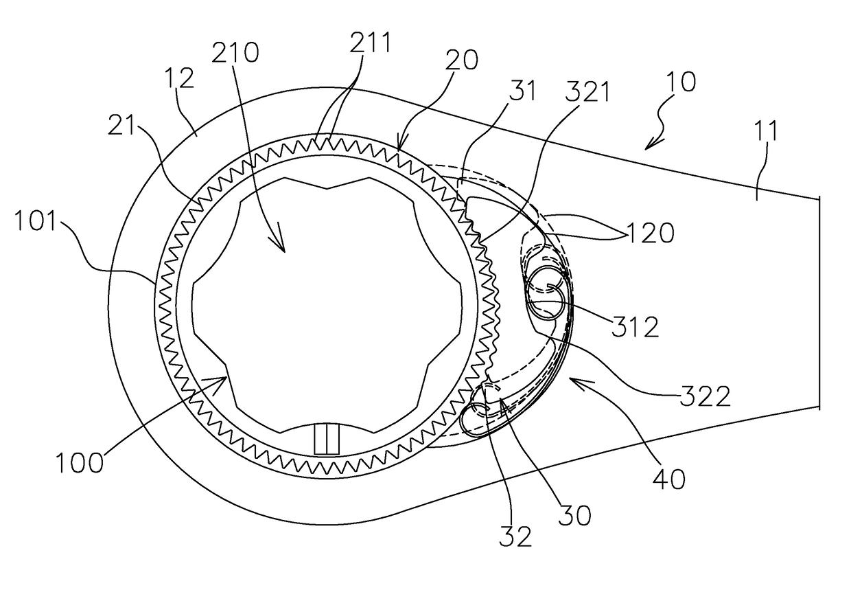
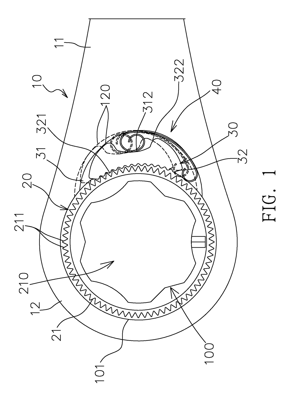
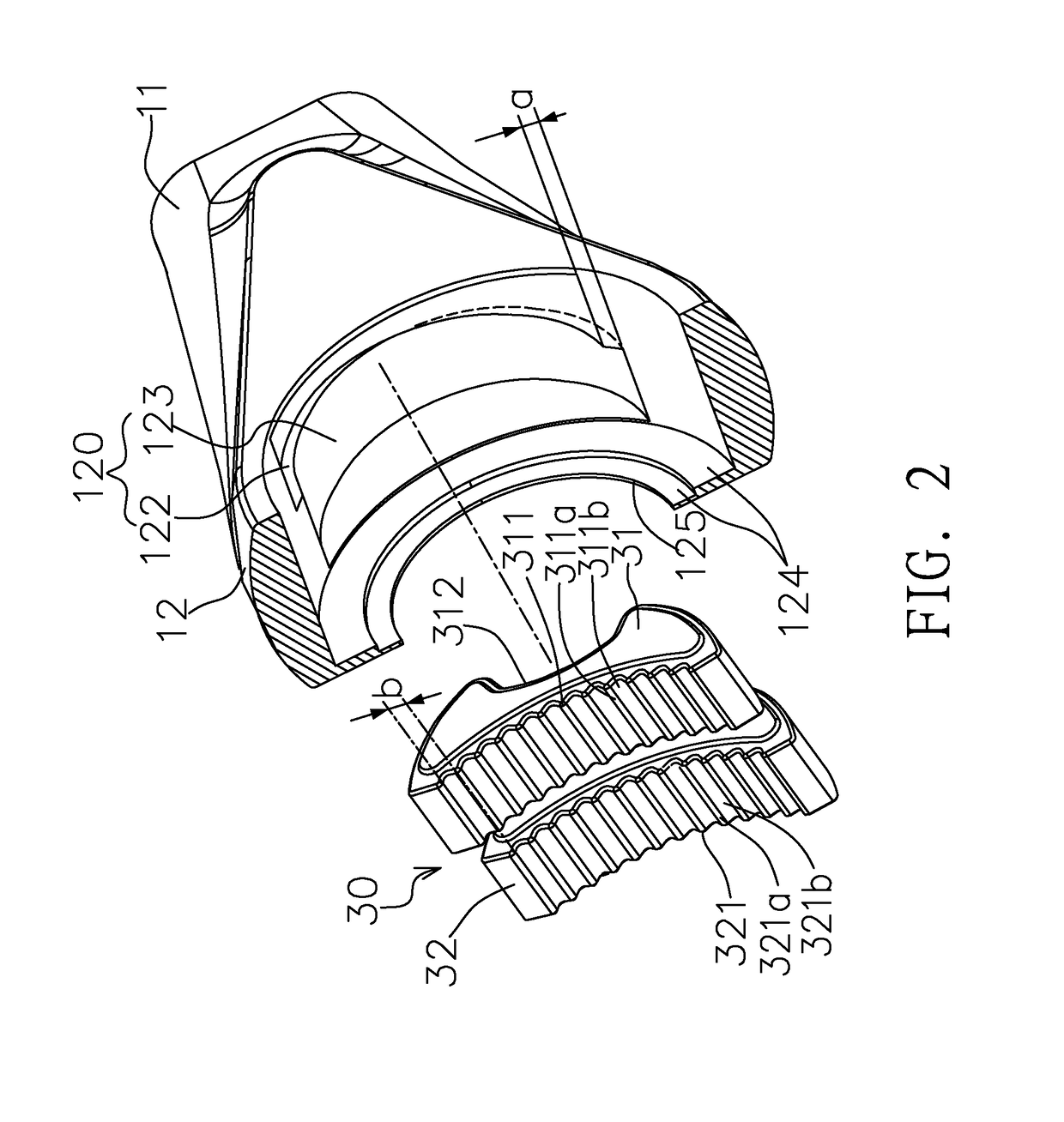
[0034]Please refer to FIG. 1 to FIG. 5, which illustrate a first preferred embodiment of a wrench structure for small-distance operations of the present invention. The embodiment has a wrench 10, a driving device 20, a latching device 30, and an elastic device 40. The wrench 10 includes a wrench handle 11 and a wrench head 12, a central portion of the wrench head 12 has an operation area 100. The operation area 100 has a ratchet accommodation ring 101. A rear end (based on the direction of FIG. 2) of the wrench head 12 corresponding to the operation area 100 has a slot area 120, and the slot area 120 further has an upper first latching groove 122 and a lower second latching groove 123 that are vertically arranged, parallel, overlapped, and connected to each other. Each of the first latching groove 122 and the second latching groove 123 has a lateral angle offset along a l...


PUM


Abstract

A wrench structure for small-distance operations includes a wrench, a driving device, a latching device and an elastic device. The wrench includes a wrench head, a central portion and a rear end which has an operation area and a slot area with two latching grooves that are vertical, parallel and overlapped with each other, each of the latching grooves having a lateral angle offset. The driving device includes a ratchet member disposed in the operation area, an outer ring portion of the ratchet member having plural driving teeth. The latching device includes two latching members, two front end surfaces of the latching members having plural teeth individually, the latching members being in the latching grooves and being connected with the plural driving teeth individually, a lateral angle offset being between the latching members. The elastic device is disposed in the slot area for urging the latching members.

Description

BACKGROUND OF THE INVENTION1. Field of the Invention[0001]The present invention generally relates to a wrench structure, more particularly to a wrench structure that is simplified in the whole structure and facilitates to fabricate, and is convenient to operate in a small space and a small distance.2. Description of the Prior Art[0002]Ratchets are commonly used for facilitating to tighten and loosen a screw / nut and other kinds of positioning workpieces. A present ratchet wrench comprises at least one head that has an operation area. The operation area has a ratchet driving member and is to accommodate a screw rod or nuts. After fitting the ratchet driving member with the screw rod / nut, a rotational force is applied to a handle for tightening and loosing the screw rod / nut. Since the ratchet wrench is in an extremely limited space, the angle and distance of rotating and pulling back the wrench may be small and short, so that the wrench does not move one-pitch distance, and it must be ...

Claims


Application Information

Patent Timeline
Patent Type & Authority Patents(United States)
IPC IPC(8): B25B13/48B25B13/46
CPCB25B13/463
Inventor WANG, YEO-MING
Owner WANG YEO MING
Why Eureka
Try Eureka