Method for determining a pitch of a camera installed in a vehicle and method for controling a light emission of at least one headlight of a vehicle.

a technology for determining the pitch of a camera and a vehicle, which is applied in the direction of instruments, television systems, image enhancement, etc., can solve the problem of large error in distance estimation, and achieve the effect of reducing the required data processing capacity, reducing the cost of resource expenditure, and efficiently generating

Inactive Publication Date: 2014-08-07
ROBERT BOSCH GMBH
View PDF4 Cites 2 Cited by
  • Summary
  • Abstract
  • Description
  • Claims
  • Application Information

AI Technical Summary

Benefits of technology

[0016]For example, a lane departure warning and / or lane keeping assistance may be improved in conjunction with a backup camera.
[0017]In the step of production, the first and / or second image gradient data may be produced with the aid of a radon transformation, in particular a radon transformation in the horizontal direction with respect to the affected camera image. The radon transformation is an integral transformation. In this case, the radon transformation may take into consideration a brightness change of adjacent pixels from multiple columns of pixels. The brightness changes in the multiple columns of pixels may be successively integrated in this case, the columns being processed successively in the horizontal direction. This specific embodiment offers the advantage that with the aid of the radon transformation, with reasonable resource expenditure, informative image gradient data may be produced based on not only one column of pixels. An image displacement value may be efficiently generated based on the image gradient data produced with the aid of radon transformation.
[0018]Furthermore, it is favorable if in the step of production, the first image gradient data are produced from a subarea of the first camera image and the second image gradient data are produced from a corresponding subarea of the second camera image. Such a specific embodiment of the present invention offers the advantage of significantly reduced required data processing capacity for the production of the first and second image gradient data, since only a small part of the first and second images has to be analyzed.
[0019]In the step of generation, the at least one image displacement value may also be generated with the aid of a cross correlation from the first image gradient data and the second image gradient data. For this purpose, the step of generation may have an estimation, and in particular a subpixel-precision estimation. The estimation on the basis of the cross correlation is highly precise, with a high resolution of less than one pixel (subpixel), for example.
[0020]In the step of ascertainment, a pitch angular velocity may be ascertained, to determine the pitch of the camera. This specific embodiment offers the advantage that the pitch may be determined in the form of the pitch angular velocity in an uncomplicated way.
[0021]In this case, in the step of ascertainment, a pitch angular velocity may be ascertained based on the at least one image displacement value, a time difference between the first camera image and the second camera image, and a focal length of the camera, to determine the pitch of the camera. This specific embodiment offers the advantage that based on the above-mentioned input variables, the pitch angular velocity may be ascertained in a simple and precise way.

Problems solved by technology

It may also be observed that the sensitivity to the pitch angle is very high and a slight change of the pitch angle may induce a large error in the distance estimation.

Method used


Image

  • Method for determining a pitch of a camera installed in a vehicle and method for controling a light emission of at least one headlight of a vehicle.
  • Method for determining a pitch of a camera installed in a vehicle and method for controling a light emission of at least one headlight of a vehicle.
  • Method for determining a pitch of a camera installed in a vehicle and method for controling a light emission of at least one headlight of a vehicle.

Examples


Embodiment Construction

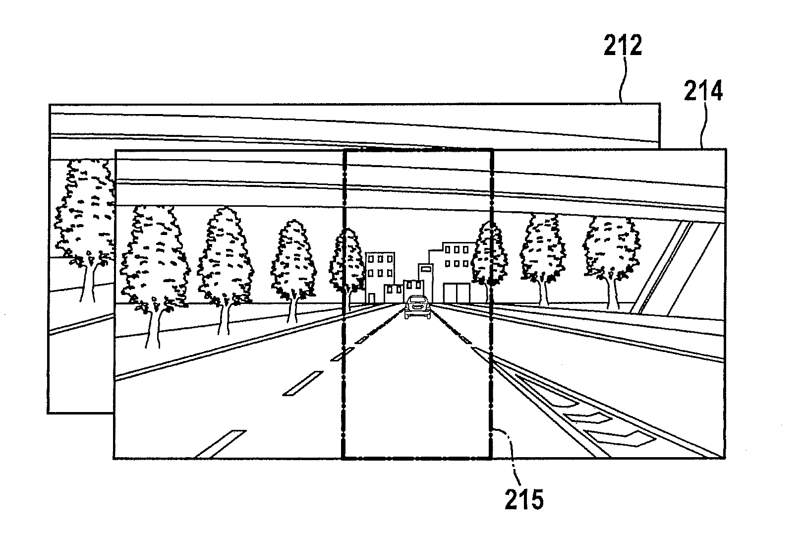
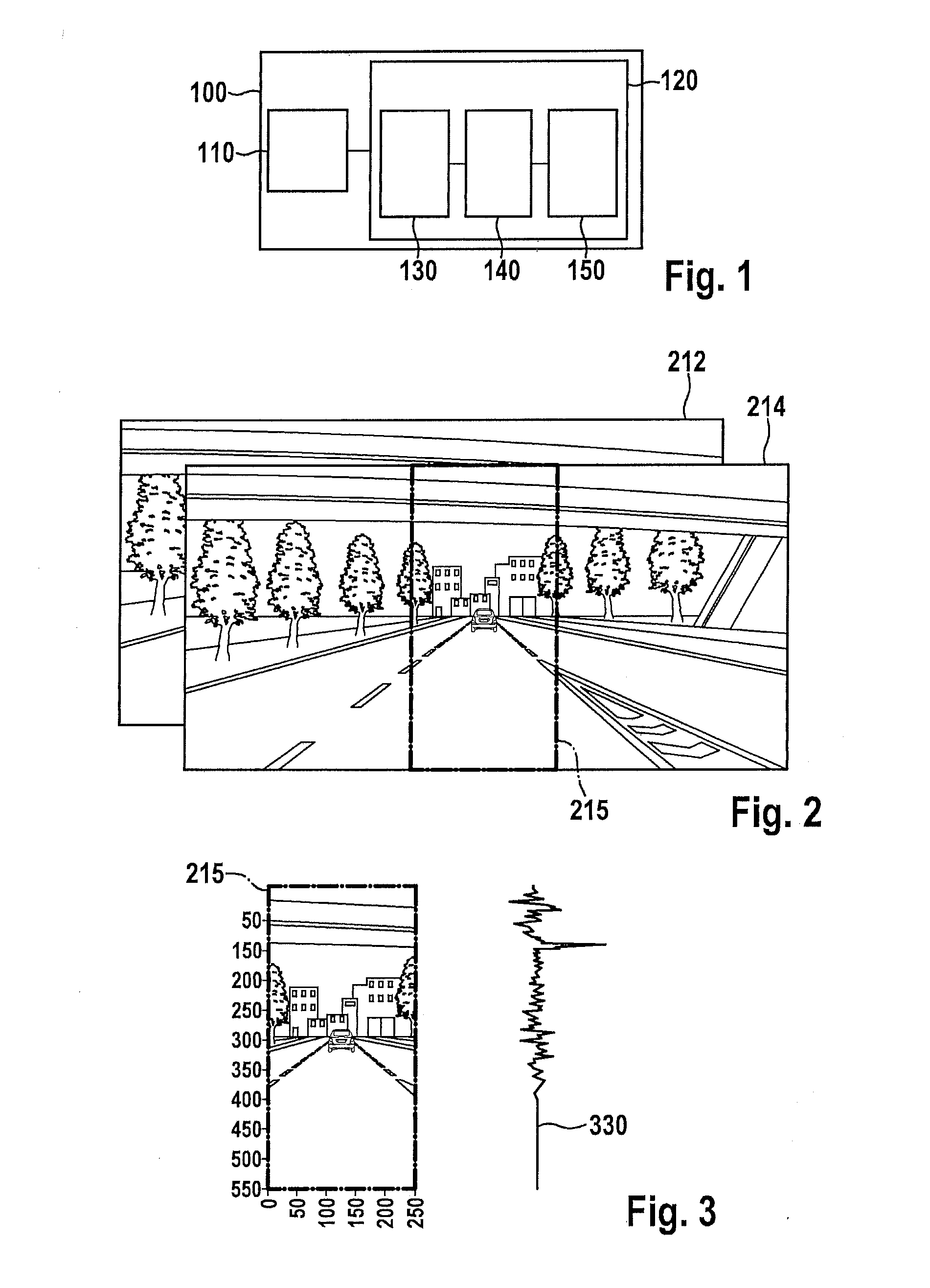
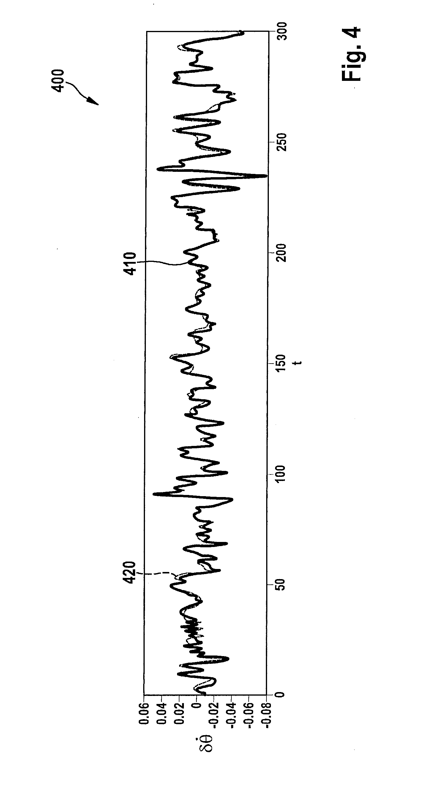
[0031]Identical or similar elements may be provided in the figures with identical or similar reference numerals, a repeated description being omitted. It is clear to those skilled in the art that these features may also be considered individually or may be combined into further combinations which are not explicitly described here. Furthermore, the present invention is possibly explained in the following description with the use of different amounts and dimensions, the present invention being understood to not be restricted to these amounts and dimensions. Furthermore, method steps according to the present invention may be executed repeatedly and in a sequence other than that described. If an exemplary embodiment includes an “and / or” link between a first feature / step and a second feature / step, this may be read to mean that the exemplary embodiment has according to one specific embodiment both the first feature / the first step and also the second feature / the second step and has accordi...


PUM


Abstract

A method for determining a pitch of a camera installed in a vehicle includes: production of first image gradient data from a first camera image, the first image gradient data representing a brightness change of adjacent pixels of the first camera image along a vertical axis of the first camera image; production of second image gradient data from a second camera image recorded subsequent to the first camera image, the second image gradient data representing a brightness change of adjacent pixels of the second camera image along a vertical axis of the second camera image; generation of an image displacement value, which represents a displacement of a pixel of the second camera image in relation to a corresponding pixel of the first camera image; and ascertainment of a pitch based on the image displacement value.

Description

BACKGROUND OF THE INVENTION[0001]1. Field of the Invention[0002]The present invention relates to a method for determining a pitch of a camera installed in a vehicle, to a method for controlling a light emission of at least one headlight of the vehicle, to a device which is designed to carry out the steps of such a method, and to a computer program product having program code which is stored on a machine-readable carrier, for carrying out such a method when the program is executed on a device.[0003]2. Description of the Related Art[0004]One of the most important safety functions which is available in a modern video-based driver assistance system is the tracking and position estimation of the preceding vehicles or obstructions in the travel direction, in order to initiate automatic full braking of the vehicle in the case of dangerously close or shrinking distances. The precision of the tracking and the distance to the vehicle or obstruction are primarily dependent on the egomotion, i....

Claims


Application Information

Patent Timeline
Patent Type & Authority Applications(United States)
IPC IPC(8): G06K9/00H04N17/00
CPCH04N17/002G06K9/00791G06T2207/10016G06T2207/20068G06T2207/30244G06T2207/30252B60Q1/10B60Q2300/132G06T7/269G06V20/56
Inventor SELLHUSEN, STEFANPARAKRAMA, THUSITHA
Owner ROBERT BOSCH GMBH
Why Eureka
Try Eureka