DJ control disc configuration optimized for DJ performance

a technology of dj control disc and turntable, which is applied in the field of audio turntables, can solve the problems of djs not having ergonomic platter configurations, djs with strobe or ornamental relief structures, and can be uncomfortable for djs during dj performance, so as to improve ergonomic finger control, improve dj performance, and improve the configuration of turntable platters

Active Publication Date: 2018-10-30
INMUSIC BRANDS
View PDF16 Cites 0 Cited by
  • Summary
  • Abstract
  • Description
  • Claims
  • Application Information

AI Technical Summary

Benefits of technology

[0008]The present invention preserves the advantages of prior art turntables and platter configurations used therewith. In addition, it provides new advantages not found in currently available turntable platter configurations and overcomes many disadvantages of such currently available turntable platter configurations.
[0009]The invention is generally directed to the novel and unique turntable platter configuration. The turntable platter configuration of the present invention includes a platter construction that is configured with an edge profile that is optimized for DJ performance. The turntable platter includes a groove on the platter edge about its periphery to allow for an improved ergonomic finger control for a DJ to alter the speed of the platter rotation. The turntable platter of the present invention also includes regularly spa

Problems solved by technology

Since the strobe dots are typically in relief, they can be somewhat abrasive to the touch, particularly when they are running past the fingers of a DJ.
Therefore, turntables with platters, with the usual strobe or ornamental reli

Method used


Image

  • DJ control disc configuration optimized for DJ performance
  • DJ control disc configuration optimized for DJ performance
  • DJ control disc configuration optimized for DJ performance

Examples


Embodiment Construction

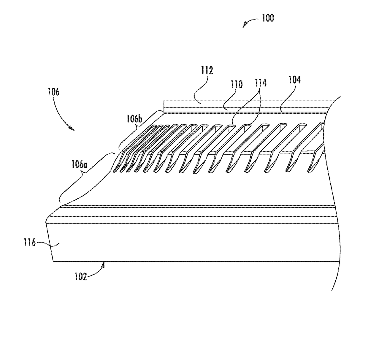
[0022]Turning first to FIG. 4, a front perspective view of the new DJ turntable platter 100 of the present is shown. A top view of the platter is shown in FIG. 5 while a side elevational view of the platter is shown in FIG. 6. FIG. 7 shows a close-up elevational view of the peripheral edge of the inventive DJ turntable platter of the present invention.

[0023]As seen in FIGS. 4-6, it can be seen that the platter 100 of the present invention includes a disc 102 with a top surface 104 and a peripheral edge, which is generally referred to as 106. A center hole 108 is also provided for installing the platter 100 to a turntable for use, which is very well known in the art and need not be discussed further herein. The top surface 104 is configured for the usual receipt of a slipmat 110 or other interim structure to the support a vinyl record 112 thereon.

[0024]Referring now to FIG. 7, details of the inventive edge peripheral profile of the platter 100 of present invention is shown in detail....


PUM


Abstract

The turntable platter configuration of the present invention includes a groove on the platter edge about its periphery to allow for an improved ergonomic finger control for a DJ to alter the speed of the platter rotation. The turntable platter configuration also includes a regularly spaced shape about the periphery of the platter to be used with a strobe for allowing the user to ensure the rate of the rotation is at the appropriate speed, such as 33 RPM or 45 RPM.

Description

CROSS REFERENCE TO RELATED APPLICATION[0001]N / ABACKGROUND OF THE INVENTION[0002]The invention relates generally to audio turntables. In particular, the present invention relates to such turntables that are used by a disc jockey (DJ) for vinyl playback.[0003]In the prior art, audio turntables for vinyl playback are very well known. They include a rotating platter that receives the vinyl disc thereon. A tone arm assembly, with a tone arm and cartridge, interfaces with the vinyl record so that audio signals can be created therefrom to the produce the desired audio. The rotating platter of the turntable that holds the vinyl typically has a beveled or straight edge. The design of this edge for an operator who is only listening to a record is primarily cosmetic.[0004]However, there are some turntable platters that contain regularly spaced dots or other shapes that, when strobed with a light, could inform the user of whether the platter was turning at a specific rate. For example, as shown...

Claims


Application Information

Patent Timeline
IPC IPC(8): G11B3/60G11B19/28G11B19/20
CPCG11B19/28G11B19/20G11B3/60
Inventor O'DONNELL, JOHNPUCKETT, SCOTTGOODWIN, ROSS H.ROMAN, CHRISTOPHER
Owner INMUSIC BRANDS
Why Eureka
Try Eureka