Apparatus and method for pile-up correction in photon-counting detector

a detector and pileup technology, applied in the field of detectors, can solve the problems of reducing the quality of the generated image, affecting the detection accuracy of the detector, and unable to determine which x-ray detection event is associated with each particular photon, so as to achieve the effect of improving the accuracy of information captur

Active Publication Date: 2018-11-06
GENERAL ELECTRIC CO
View PDF102 Cites 4 Cited by
  • Summary
  • Abstract
  • Description
  • Claims
  • Application Information

AI Technical Summary

Benefits of technology

[0007]A technical effect of some embodiments described herein may be an improved and accurate capturing of information pertaining to X-ray detection events (achieved, e.g., via a more accurate photon-counting detector). Embodiments may be associated with systems and / or computer-readable medium storing instructions to perform any of the methods described herein.

Problems solved by technology

As a result, a photon-counting detector may experience a “pile-up” condition where X-ray photons arrive at the detector at such a rate that it may be difficult to determine which X-ray detection event is associated with each particular photon.
Pile up causes error in both the estimation of the number and energy of the detected photons; these errors may cause the quality of a generated image to be degraded.

Method used


Image

  • Apparatus and method for pile-up correction in photon-counting detector
  • Apparatus and method for pile-up correction in photon-counting detector
  • Apparatus and method for pile-up correction in photon-counting detector

Examples


embodiment 800

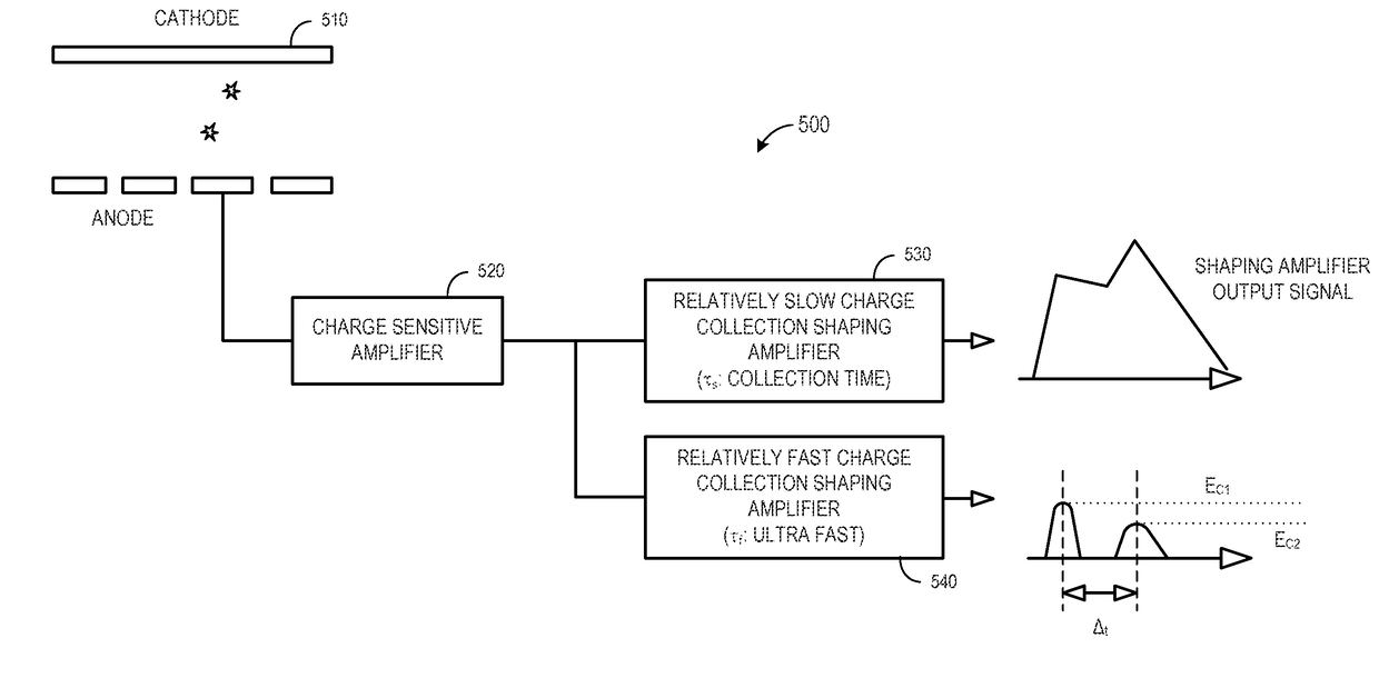
[0050]In the “multiple-threshold mode,” a relatively fast charge collection shaping amplifier (high-bandwidth, band-pass filter) may record a photon in one of a plurality of energy bins based on an energy threshold, and the number of photons in each bin is then used to allocate the first portion of the total amount of energy to the first event and the second portion of the total amount of energy to the second event. FIG. 8 illustrates a multi-bin embodiment 800 in accordance with some embodiments. In this embodiment, standard slow shaper and ADC or Charge-to Digital Convertor (“QDC”) output at 810 are used, along with validation of the signal from a fast shaper signal, to determine if there was a pile-up condition at 820. If there was no pile up, all of the energy (ETOTAL) is associated with a single event at 830.

[0051]If there was a pile-up condition at 820, thresholds may be applied at 840 and a photon might be assigned to one of a number of bins. For example, in the case of pile-...

embodiment 1000

[0056]In the “time correction mode,” a first timing value may be recorded in connection with the first event and a second timing value may be recorded in connection with the second event, and the allocation of ETOTAL is further apportioned based on the first and second timing values. For example, the difference between the two time values may be used to apply a second-order correction on the signal. FIG. 10 illustrates an embodiment 1000 utilizing a timing difference correction in accordance with some embodiments. As before, standard slow shaper and ADC (or QDC) output at 1010 are used, along with validation of the signal from a fast shaper signal, to determine if there was a pile-up condition at 1020. If there was no pile up, all of the energy (ETOTAL) is associated with a single event at 1030. Moreover, the two fast signals are used to allocate E1 and E2 at 1040 and 1050 as described with respect to steps 940 and 950 in FIG. 9.

[0057]According to some embodiments, this mode adds ex...


PUM


Abstract

Some embodiments are associated with an input signal comprising a first and a second photon event incident on a photon-counting semiconductor detector. A relatively slow charge collection shaping amplifier may receive the input signal and output an indication of a total amount of energy associated with the superposition of the first and second events. A relatively fast charge collection shaping amplifier may receive the input signal and output an indication that is used to allocate a first portion of the total amount of energy to the first event and a second portion of the total amount of energy to the second event.

Description

BACKGROUND[0001]The invention relates to detectors and, more particularly, to an apparatus and method for pile-up correction in a photon-counting detector for medical imaging and similar applications.[0002]X-ray computed tomography imaging, also referred to as Computed Tomography (CT) or Computed Axial Tomography (CAT), employs computer-processed X-ray projections to generate images of the interior of an object of interest. These systems generally successively emit and detect photons in the X-ray energy range, directed toward an object, so as to generate a plurality of consecutive-projection data of the object's contents. The projection data may then be used to generate a three-dimensional image of the inside of the object. The three-dimensional image may be used for diagnostic and therapeutic purposes in various medical disciplines, but may also be used in a wide variety of other contexts, such as baggage inspection and industrial part inspection.[0003]CT photon-counting detection ...

Claims


Application Information

Patent Timeline
Patent Type & Authority Patents(United States)
IPC IPC(8): A61B6/03A61B6/00
CPCA61B6/4241A61B6/032A61B6/4208A61B6/54A61B6/4435A61B6/4441A61B6/4233A61B6/461A61B6/467A61B6/5205
Inventor FU, GENGEDIC, PETER MICHAELYANOFF, BRIAN DAVIDGUO, JIANJUNLOBASTOV, VLADIMIR A.JIN, YANNAN
Owner GENERAL ELECTRIC CO
Why Eureka
Try Eureka