Integrated turboshaft engine

a turboshaft engine and integrated technology, applied in the field of engines, can solve the problems of low power density of piston and rotary engines compared to gas turbines

Active Publication Date: 2018-11-06
GENERAL ELECTRIC CO
View PDF18 Cites 15 Cited by
  • Summary
  • Abstract
  • Description
  • Claims
  • Application Information

AI Technical Summary

Problems solved by technology

However, despite using turbochargers, the engines such as piston and rotary engines are low in power density compared to gas turbines.

Method used


Image

  • Integrated turboshaft engine
  • Integrated turboshaft engine
  • Integrated turboshaft engine

Examples


Embodiment Construction

[0011]When introducing elements of various embodiments of the present technology, the articles “a,”“an,”“the,” and “said” are intended to mean that there are one or more of the elements. The terms “comprising,”“including,” and “having” are intended to be inclusive and mean that there may be additional elements other than the listed elements. Any examples of operating parameters are not exclusive of other parameters of the disclosed examples.

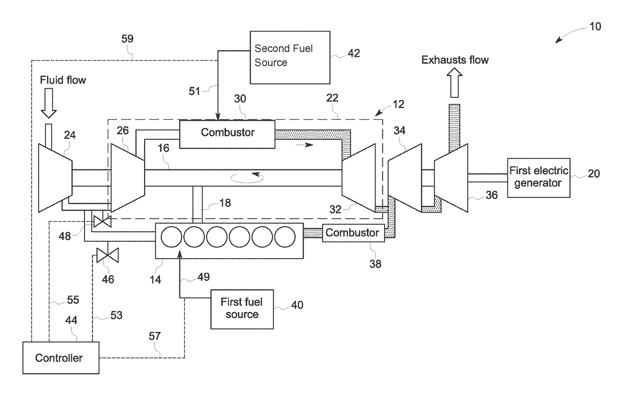
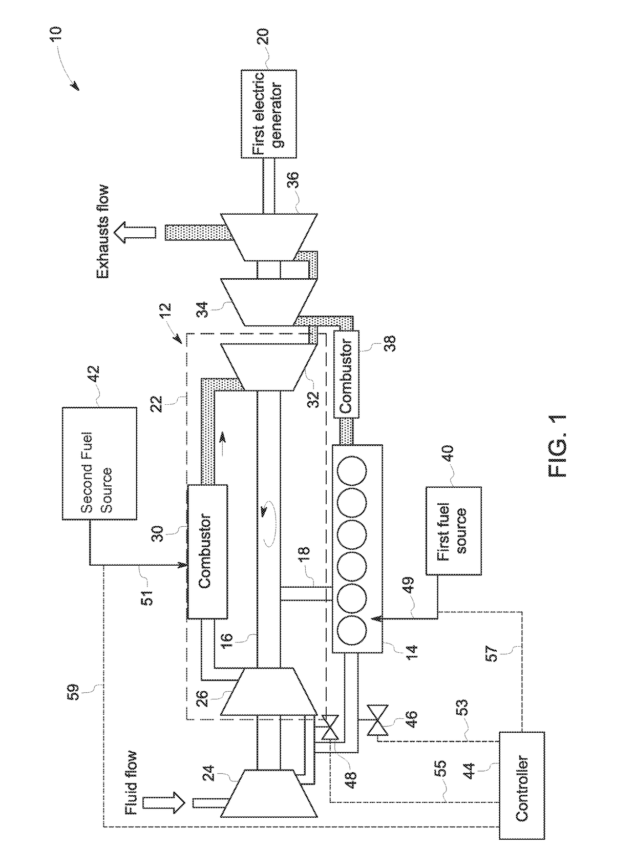
[0012]FIG. 1 schematically shows a system 10 having an integrated turbo-shaft engine having a turbocharger assembly 12 in accordance with an example of the present technology. The system 10 includes an engine 14 coupled with a primary shaft 16 via a gear subsystem 18 that drives a first electric generator 20 for generating electrical power. The gear subsystem 18 may include two or more gears that provide transmission of power from the engine 14 to the primary shaft 16. The turbocharger assembly 12 includes a gas turbine engine 22 configured for d...


PUM


Abstract

A system includes an engine coupled with a primary shaft that drives a first electric generator for generating electrical power via a gear subsystem. The system also includes a turbocharger assembly having at least one gas turbine engine configured for driving the primary shaft and coupled in parallel with the engine. The turbocharger assembly includes multiple compressors configured to provide a flow of compressed fluid into both the engine and the at least one gas turbine engine and multiple turbines configured to utilize exhausts from both the engine and the one gas turbine for driving the primary shaft. Further, the system includes a controller configured to operate a plurality of valves for controlling optimal intake fluid pressure into the engine and the turbocharger assembly and fuel injections into the engine and the at least one gas turbine engine.

Description

BACKGROUND[0001]The present technology relates generally to engines and, in particular, to systems and methods having an integrated turbo-shaft engine.[0002]The capability of modern engines to produce more power from a given cylinder displacement has been steadily increased due to engineering innovation and development. Modern engines utilize higher charged air pressure provided by turbochargers to generate more power than their previous generation counterparts. The amount of power obtained from an engine depends upon how much fuel is burned in it, and upon the amount of air available in the engine. Therefore, by providing more air into the engine cylinder more fuel can be burned and the power generated can be increased. Turbocharging is a technique used to increase the amount of air introduced into each cylinder, typically by a positive pressure that exceeds the then reigning pressure in the cylinder. Exhaust gas from the engine typically drives the turbocharger. This exhaust gas d...

Claims


Application Information

Patent Timeline
Patent Type & Authority Patents(United States)
IPC IPC(8): F02C3/13F02C6/12F02C6/00F02C6/08F02D41/00F01D15/10F02C3/10F02B63/04F02C6/20
CPCF02B63/04F01D15/10F02C3/10F02C3/13F02C6/00F02C6/12F02C6/20F02D41/0007F02C6/08Y02T10/144F05D2220/40F05D2220/76Y02T10/12
Inventor PRIMUS, ROY JAMESKLINGBEIL, ADAM EDGARJOSHI, NARENDRA DIGAMBERAKINYEMI, OMOWOLEOLA CHUKWUEMEKALAVERTU, THOMAS MICHAEL
Owner GENERAL ELECTRIC CO
Why Eureka
Try Eureka