Dynamic tire pressure regulator for bicycles
a technology of dynamic tire pressure regulator and bicycle, which is applied in the direction of bicycle tyres, tyre parts, tyre measurements, etc., can solve the problems of large tires, inefficient and awkward, and the most complex step, so as to avoid affecting the wheel weight balan
- Summary
- Abstract
- Description
- Claims
- Application Information
AI Technical Summary
Benefits of technology
Problems solved by technology
Method used
Image
Examples
first embodiment
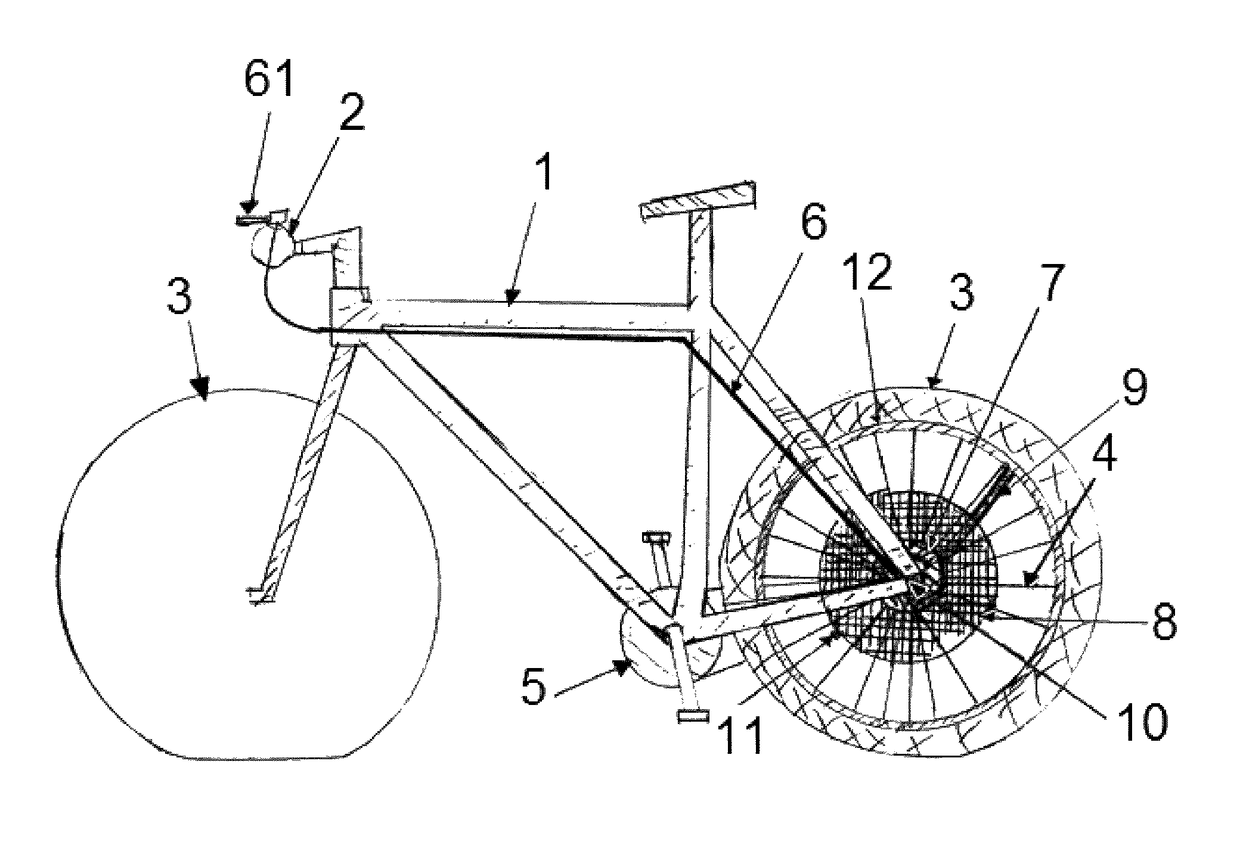
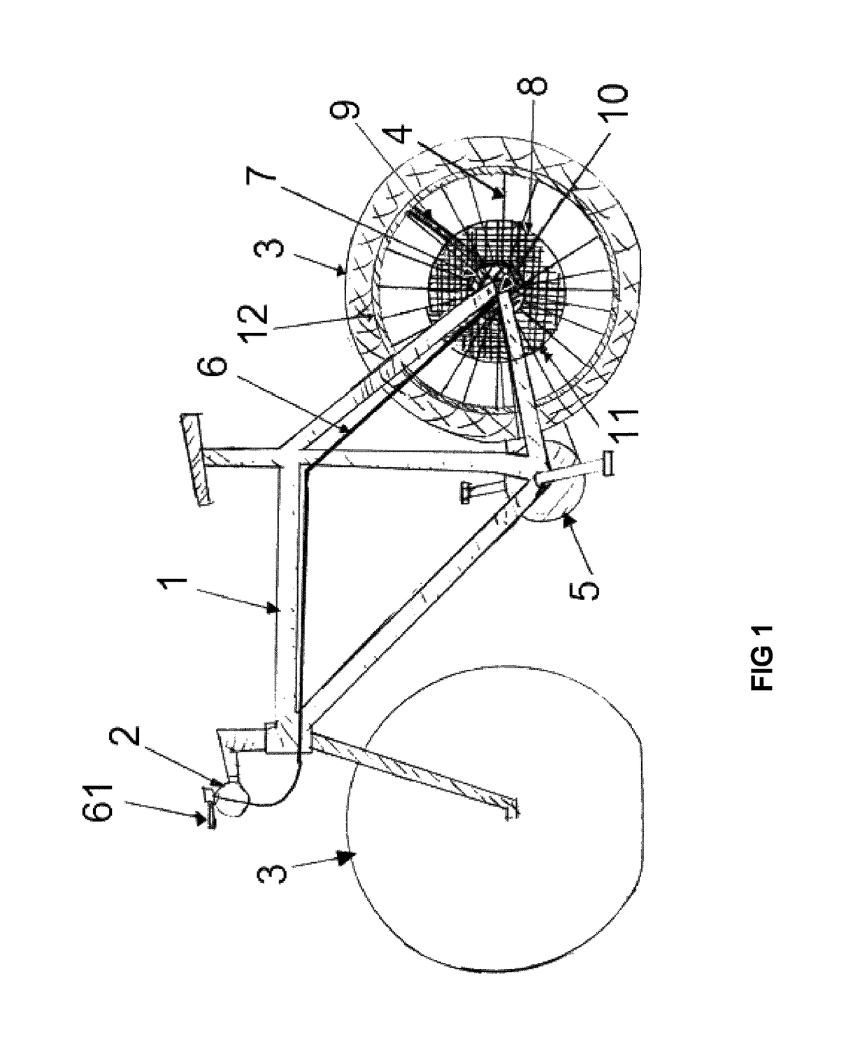
[0028]Referring now to the invention in more detail, in FIG. 1 there is shown a bicycle in a mountain-biking oriented design depicting the major components relevant to this invention in its There is shown frame 1 with handlebar 2, front and back tires 3. The back wheel is detailed further in spokes 4, main axle 10, rim 12, central hub body 7, air reservoir 8, main system air inlet 11, and air-conduct 9. The central hub 7 with regulation pump is controlled via control cable 6, which itself is conveniently actuated via 3-position handle 61. Drive train 5 is included for illustration purposes only.
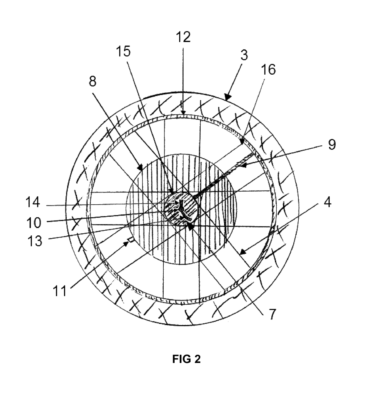
[0029]In more detail, and referring to the first embodiment of the invention in FIG. 2, there is shown a more detailed left-hand view of the wheel, including (back) tire 3, multiple spokes 4 attached to hub 7 with regulating pump on eyelets 15 and to rim 12 via nipples 16. In between left and right-hand-side spokes, and surrounding hub body 7 there is the air reservoir 8, with system air-inl...
second embodiment
[0030]Referring to the invention in FIG. 3, there is shown a more detailed left-hand view of the wheel, including tire 3, multiple spokes 4 attached to hub body 7 on eyelets 15 and to rim 12 via nipples 16. Within the tire 3, and directly on top of the rim 12 there is the air reservoir 18, with system air-inlet valve 11, which goes across rim 12. The hub body 7 is mounted on central axle 10 featuring axle-to-frame lock 13 and pressure control bar 14. Finally the hub body 7 is connected to the tire with air conduct 9 across rim 12, and with the air reservoir 18 with air conduct17 also across rim 12. The disk brake rotor is not featured for clarity.
[0031]In further detail, and referring to the second embodiment of the invention as shown in FIG. 4, there is shown a cross-section of the “top” of the wheel along section line I-I of FIG. 3, with a partial depiction of tire 3 and its main air chamber 20 mounted on rim 12 using tire-beads 21. Featured inside tire 3, above rim 12 and between...
third embodiment
[0045]Still referring to the invention, FIG. 9 shows a detailed cross section of the middle of the back wheel perpendicular to FIG. 8 at the high where all the air-outflow check valves 41 are located along section line III-III in FIG. 8. In it all the multiple chambers 40 are depicted in different stages of air compression (those on the right hand-side) and (those on the left hand-side) while the top and bottom chambers are in their most relaxed and compressed states respectively. FIG. 9 also provides a more detailed depiction on how the annular air-channel 43 can be constructed around hub-body 7 and then routed on the “top” section towards the rest of the embodiment. Not depicted here, annular air channel 44 can be constructed in a similar fashion.
[0046]The working principle of the third embodiment (FIGS. 8 and 9) remains substantially the same as for the first embodiment, with main differences residing in how the air is compressed by the core of the pump in the tire-deflation stat...
PUM
 Abstract
Description
Claims
Application Information
 - R&D
- Intellectual Property
- Life Sciences
- Materials
- Tech Scout
- Unparalleled Data Quality
- Higher Quality Content
- 60% Fewer Hallucinations
Browse by: Latest US Patents, China's latest patents, Technical Efficacy Thesaurus, Application Domain, Technology Topic, Popular Technical Reports.
© 2025 PatSnap. All rights reserved.Legal|Privacy policy|Modern Slavery Act Transparency Statement|Sitemap|About US| Contact US: help@patsnap.com


