Dynamic tire pressure regulator for bicycles

a technology of dynamic tire pressure regulator and bicycle, which is applied in the direction of bicycle tyres, tyre parts, tyre measurements, etc., can solve the problems of large tires, inefficient and awkward, and the most complex step, so as to avoid affecting the wheel weight balan

Active Publication Date: 2017-01-19
VERSEC
View PDF9 Cites 10 Cited by
  • Summary
  • Abstract
  • Description
  • Claims
  • Application Information

AI Technical Summary

Benefits of technology

[0014]Aspects of the invention allow for selecting the desired tire pressure by the rider conveniently from the handlebar while riding via mechanical actuation or electronic control. Aspects of the invention allow for an unlimited amount of tire-pressure changes within a pre-determined pressure range. No mechanical load is created when the tire pressure is held static. According to aspects of the invention, the device or assembly works as an entirely closed system, overcoming air-quality and / or air-volume limitations. As an advantage, devices or assemblies according to the invention can be installed in most existing mountain bikes without modifications to the frame, drive-train or brakes. Finally, as an additional advantage, devices or assemblies according to the invention are relatively lightweight, and do not disrupt the weight balance of the wheel.

Problems solved by technology

Step 1 is by far the most complex and numerous designs to address it exist.
In car and truck applications, a more complex system may exist with the ability to manage the pre-set maximum tire pressure while riding the vehicle, either by pure mechanical or electronically controlled means.
Although these large tires may seem inefficient and awkward to ride for those not versed in the state of the art, when set at relatively low pressures, they provide for much more energy efficient, controllable and comfortable riding over rugged terrain when compared to thin and high pressure tires.
However, the large tires and very low pressures make them relatively inefficient when riding over smooth terrain.
Actually, the larger the tire, the more the pressure-efficiency balance between rugged and smooth terrain becomes sensitive, and in many circumstances, it is impossible to pre-set the tire at an ideal pressure given the typical mixed-terrain circuits where these mountain bikes are usually ridden.
Therefore, incorporation of a tire-pressure regulation device will be a priori extremely convenient in these mountain biking applications; however, none of the existing state of the art has achieved any significant usage in this fields because:
In mountain biking applications it is impractical to filter efficiently the incoming atmosphere air given the variety of riding circuits featuring large quantities of dust, dirt and mud;
It is impractical to incorporate reservoirs featuring large capacity of highly compressed air, and when these are incorporated, only a few full inflation cycles can be achieved given the relatively large size of the tires;
Alternative liquefied-CO2 based reservoirs have a similar cycle-limitation, and they are not compatible with most tubeless systems because CO2 “corrupts” the sealing properties of the dedicated sealing liquid incorporated inside these tires;
The systems feature none or limited ability to determine set-tire-pressure without dismounting the bike.
However, the document presents a high degree of mechanical load, it is very heavy as it unbalances the wheel, and it is wholly incompatible with current mountain bike frame, drive train and wheel technologies, and finally, it cannot be directly controlled via mechanical means.
However, the vane pump is configured such as the pump rotor is static with respect to the vehicle's main axle and therefore the pump operation cannot be controlled independently of the wheel's motion.
This creates continuous mechanical load and it cannot be used as unique single control device to change the tire pressure at will.
And finally, due to the intended field of application, the described embodiments are also wholly incompatible with current mountain bike frame, drive train and wheel technologies.

Method used


Image

  • Dynamic tire pressure regulator for bicycles
  • Dynamic tire pressure regulator for bicycles
  • Dynamic tire pressure regulator for bicycles

Examples


first embodiment

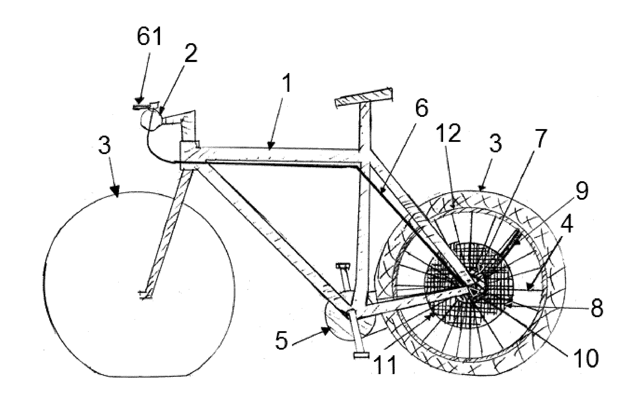
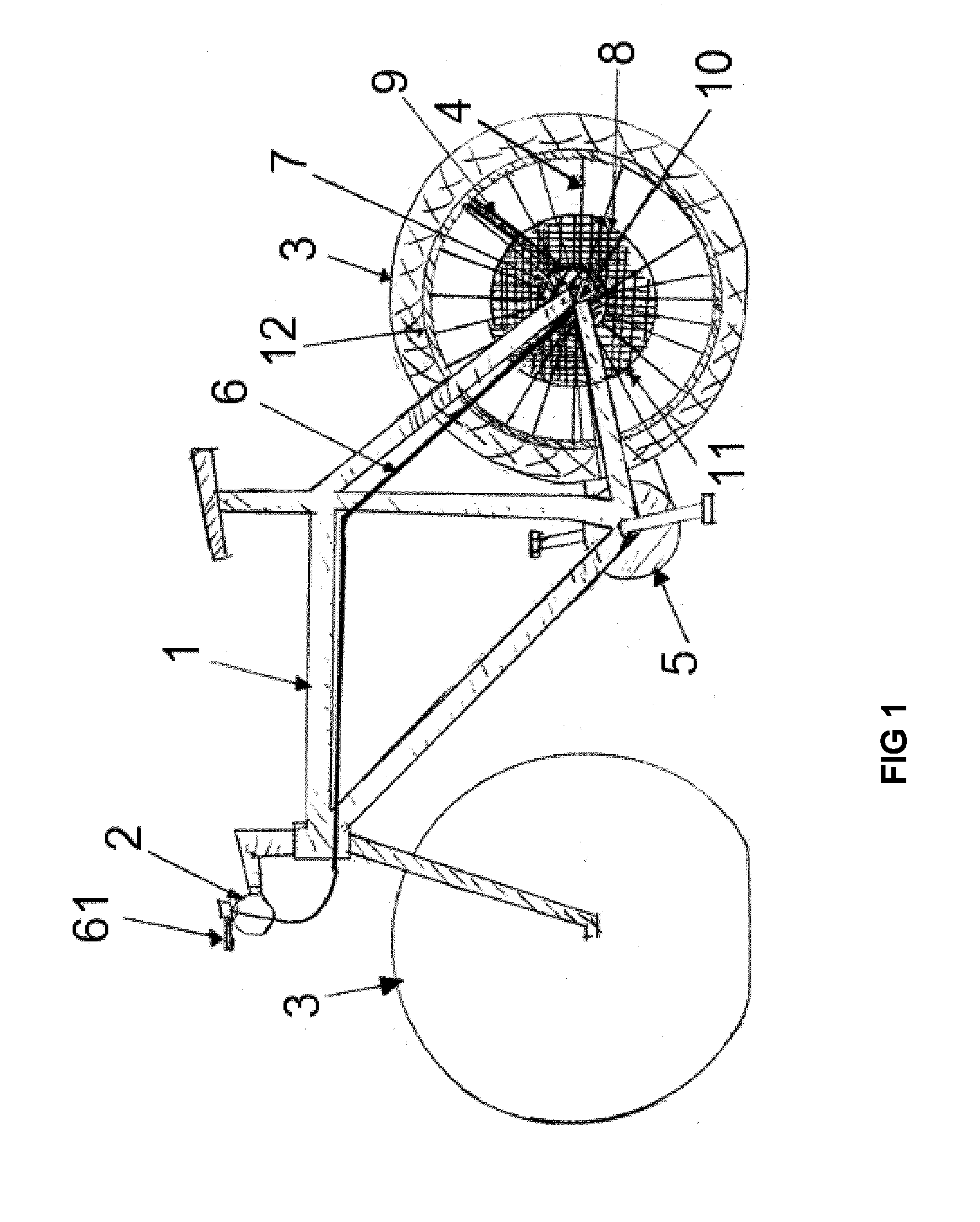
[0027]Referring now to the invention in more detail, in FIG. 1 there is shown a bicycle in a mountain-biking oriented design depicting the major components relevant to this invention in its There is shown frame 1 with handlebar 2, front and back tires 3. The back wheel is detailed further in spokes 4, main axle 10, rim 12, central hub body 7, air reservoir 8, main system air inlet 11, and air-conduct 9. The central hub 7 with regulation pump is controlled via control cable 6, which itself is conveniently actuated via 3-position handle 61. Drive train 5 is included for illustration purposes only.

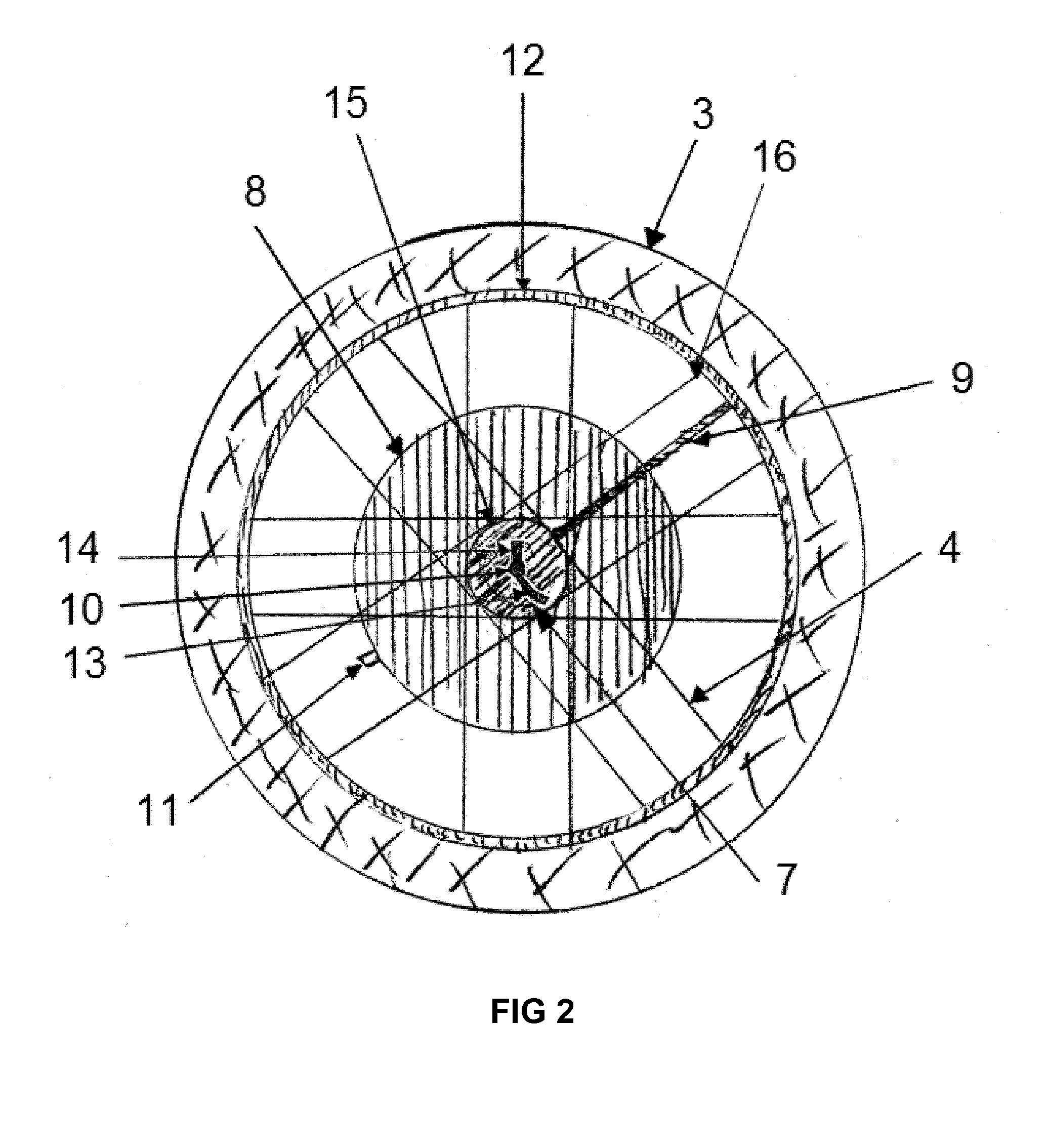
[0028]In more detail, and referring to the first embodiment of the invention in FIG. 2, there is shown a more detailed left-hand view of the wheel, including (back) tire 3, multiple spokes 4 attached to hub 7 with regulating pump on eyelets 15 and to rim 12 via nipples 16. In between left and right-hand-side spokes, and surrounding hub body 7 there is the air reservoir 8, with system air-inl...

second embodiment

[0029]Referring to the invention in FIG. 3, there is shown a more detailed left-hand view of the wheel, including tire 3, multiple spokes 4 attached to hub body 7 on eyelets 15 and to rim 12 via nipples 16. Within the tire 3, and directly on top of the rim 12 there is the air reservoir 18, with system air-inlet valve 11, which goes across rim 12. The hub body 7 is mounted on central axle 10 featuring axle-to-frame lock 13 and pressure control bar 14. Finally the hub body 7 is connected to the tire with air conduct 9 across rim 12, and with the air reservoir 18 with air conduct 17 also across rim 12. The disk brake rotor is not featured for clarity.

[0030]In further detail, and referring to the second embodiment of the invention as shown in FIG. 4, there is shown a cross-section of the “top” of the wheel along section line I-I of FIG. 3, with a partial depiction of tire 3 and its main air chamber 20 mounted on rim 12 using tire-beads 21. Featured inside tire 3, above rim 12 and betwee...

third embodiment

[0044]Still referring to the invention, FIG. 9 shows a detailed cross section of the middle of the back wheel perpendicular to FIG. 8 at the high where all the air-outflow check valves 41 are located along section line III-III in FIG. 8. In it all the multiple chambers 40 are depicted in different stages of air compression (those on the right hand-side) and (those on the left hand-side) while the top and bottom chambers are in their most relaxed and compressed states respectively. FIG. 9 also provides a more detailed depiction on how the annular air-channel 43 can be constructed around hub-body 7 and then routed on the “top” section towards the rest of the embodiment. Not depicted here, annular air channel 44 can be constructed in a similar fashion.

[0045]The working principle of the third embodiment (FIGS. 8 and 9) remains substantially the same as for the first embodiment, with main differences residing in how the air is compressed by the core of the pump in the tire-deflation stat...


PUM


Abstract

A wheel hub assembly of a bicycle wheel is disclosed that include a wheel axle, a rotary pump that may be composed of a pump housing, a pump rotor, a first fluid port configured for fluidly coupling to a pneumatic tire and a second fluid port configured for fluidly coupling to a fluid reservoir. The assembly allows for conveniently and efficiently modifying the tire pressure in bicycles at will while riding, in as many cycles as desired and without contaminating the air inside the tires.

Description

[0001]The present invention is related to the technical field of devices for regulating pressure in wheels with pneumatic tires.[0002]More particularly, the present invention is in the technical field of devices allowing regulating the pressure of the pneumatic tires on bicycles while riding them.BACKGROUND OF THE INVENTION[0003]Although there are numerous examples of prior art in this field, such as WO 2013 / 075675, the current invention overcomes major flaws that have prevented them from widespread use in the field of bicycles featuring large tires until now. Most of the current state of the art concentrates in making sure the tire is inflated to an adequate pre-selected pressure by:Step 1: Acquiring air from the atmosphere and adding into the tire using a pump or similar mechanical device; or acquiring air from a pre-pressurized reservoir and adding it into the tire using valve or similar regulation device:Step 2: If necessary, releasing back air into the atmosphere should the tir...

Claims


Application Information

Patent Timeline
Patent Type & Authority Applications(United States)
IPC IPC(8): B60C23/00F04B45/04B60C23/12
CPCB60C23/004B60C2200/12F04B45/04B60C23/12B60C23/127
Inventor SERRET AVILA, JAVIERVERSTRAETE, MATHIJS
Owner VERSEC
Why Eureka
Try Eureka