Vehicle safety control apparatus and method using cameras

a safety control and camera technology, applied in the direction of pedestrian/occupant safety arrangement, television system, instruments, etc., can solve the problems of insufficient light representation, limitation in preventing traffic accidents in advance, and insufficient use of cameras, so as to achieve efficient increase the rate of image recognition

Active Publication Date: 2018-11-13
HL KLEMOVE CORP
View PDF16 Cites 0 Cited by
  • Summary
  • Abstract
  • Description
  • Claims
  • Application Information

AI Technical Summary

Benefits of technology

[0008]Therefore, it is one aspect of the present invention to provide a vehicle safety control apparatus and method using cameras that may prevent a traffic accident from occurring in advance while providing convenience of driving for a driver because an image recognition rate may be efficiently increased for a current object during running.

Problems solved by technology

However, the conventional camera is disadvantageous in that a color of at least one light source of a headlight and a taillight of another vehicle and a signal light is not properly represented (saturation).
On the other hand, the IR camera is not used in the daytime at which illumination is high.
Also, a 650 nm cut-off camera as the conventional camera does not photograph a lane covered with a shade (guardrail or tree) or does not generate images of a lane, other vehicles, etc. in a tunnel.
Because this conventional camera has limitation in providing convenience of driving a the driver unfamiliar with the driving due to degradation of the recognition rate for a current object during running, there is limitation in preventing a traffic accident from occurring in advance.

Method used


Image

  • Vehicle safety control apparatus and method using cameras
  • Vehicle safety control apparatus and method using cameras
  • Vehicle safety control apparatus and method using cameras

Examples


first embodiment

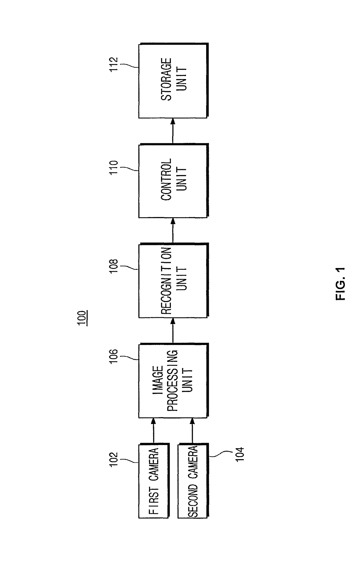
[0046]FIG. 1 is a block configuration diagram illustrating a vehicle safety control apparatus using cameras according to the present invention.

[0047]Referring to FIG. 1, the vehicle safety control apparatus 100 using the cameras according to the first embodiment of the present invention includes a first camera 102, a second camera 104, an image processing unit 106, a recognition unit 108, a control unit 110, and a storage unit 112.

[0048]The first camera 102 is provided to photograph light and shade of a current object during running, and the second camera 104 is provided to photograph a color of the current object during the running.

[0049]Here, although no illustrated, the first camera 102 may include a bright lens (not illustrated) configured to capture a bright image by passing IR light, and the second camera 104 may include a dark lens (not illustrated) configured to capture a dark image by blocking IR light.

[0050]Here, the bright lens (not illustrated) of the first camera 102 ma...

second embodiment

[0077]FIG. 4 is a block configuration diagram illustrating a vehicle safety control apparatus using cameras according to the present invention.

[0078]Referring to FIG. 4, like the vehicle safety control apparatus (100 in FIG. 1) using the cameras according to the first embodiment of the present invention, the vehicle safety control apparatus 400 using the cameras according to the second embodiment of the present invention includes a first camera 102, a second camera 104, an image processing unit 106, a recognition unit 108, a control unit 110, and a storage unit 112.

[0079]Functions and organic connection relations of elements of the vehicle safety control apparatus 400 using the cameras according to the second embodiment of the present invention are the same as those of the vehicle safety control apparatus (100 in FIG. 1) using the cameras according to the first embodiment of the present invention, and a detailed description thereof will thus be omitted.

[0080]Here, the vehicle safety...

third embodiment

[0093]FIG. 7 is a block configuration diagram illustrating a vehicle safety control apparatus using cameras according to the present invention.

[0094]Referring to FIG. 7, like the vehicle safety control apparatus (100 in FIG. 1) using the cameras according to the first embodiment of the present invention, the vehicle safety control apparatus 700 using the cameras according to the third embodiment of the present invention includes a first camera 102, a second camera 104, an image processing unit 106, a recognition unit 108, a control unit 110, and a storage unit 112.

[0095]Functions and organic connection relations of elements of the vehicle safety control apparatus 700 using the cameras according to the third embodiment of the present invention are the same as those of the vehicle safety control apparatus (100 in FIG. 1) using the cameras according to the first embodiment of the present invention, and a detailed description thereof will thus be omitted.

[0096]Here, the vehicle safety c...


PUM


Abstract

A vehicle safety control apparatus using cameras includes a first camera configured to photograph light and shade of a current object during running, a second camera configured to photograph a color of the current object during the running, an image processing unit configured to perform image processing on first current object image data captured by the first camera and second current object image data captured by the second camera, a recognition unit configured to recognize the first and second current object image data on which the image processing unit has performed the image processing, a storage unit configured to cause the recognized data to match preset reference object-specific data and separately store the data matching the preset reference object-specific data; and a control unit configured to receive the recognized data and deliver a storage command to the storage unit.

Description

CROSS-REFERENCE TO RELATED APPLICATION[0001]This application claims the benefit of Korean Patent Application No. 10-2013-0095103, filed on Aug. 12, 2013 in the Korean Intellectual Property Office, the disclosure of which is incorporated in its entirety herein by reference.BACKGROUND1. Field[0002]Embodiments of the present invention relate to a vehicle safety control apparatus and method using cameras.2. Description of the Related Art[0003]In general, in order to improve a field of view at night, a camera having a bright lens of a low F-number or an infrared (IR) camera is used as a camera installed in a conventional vehicle.[0004]However, the conventional camera is disadvantageous in that a color of at least one light source of a headlight and a taillight of another vehicle and a signal light is not properly represented (saturation).[0005]On the other hand, the IR camera is not used in the daytime at which illumination is high. Also, a 650 nm cut-off camera as the conventional camer...

Claims


Application Information

Patent Timeline
Patent Type & Authority Patents(United States)
IPC IPC(8): B60W30/08G06K9/62G06K9/00
CPCB60W30/08G06K9/00791G06K9/6201G06K9/6289G06K9/00825B60R2300/80G06V20/56G06V10/803G06F18/251B60R1/00B60R21/00G06T1/00G06T7/00H04N5/77H04N23/00G06V20/584G06F18/22
Inventor KIM, MYUNG-WOO
Owner HL KLEMOVE CORP
Why Eureka
Try Eureka