Coupling module for forming an interface between the cabin of a passenger bridge and an airplane

a technology of coupling modules and passenger bridges, which is applied in bridge applications, bridges, bridge construction, etc., can solve the problems of complexness and achieve the effect of reducing the construction effort of coupling modules

Active Publication Date: 2018-11-20
HUBNER GMBH
View PDF8 Cites 0 Cited by
  • Summary
  • Abstract
  • Description
  • Claims
  • Application Information

AI Technical Summary

Benefits of technology

[0012]A key idea of the invention is the mechanical simplification of the design of the coupling module, wherein a pendulum frame is, for example, also covered and is co-supported by the floor arrangement. The floor arrangement can be fastened to the cabin in a correspondingly loadable manner by means of the design in accordance with the invention, with the pivotability of the floor arrangement at the cabin being maintained. The floor arrangement is thus no longer suspended by the projecting roof or at its pendulum frame; the invention rather provides the advantage that the projecting roof and, for example, also the pendulum frame, so-to-say stand on the floor arrangement, that is they are arranged indirectly or even directly. A substantial advantage can be seen in the fact that a relative positional change between the floor arrangement and the projecting roof no longer results and a fixed arrangement of the projecting roof at the floor arrangement can be provided.
[0014]The arrangement of the coupling module at the cabin by means of a support body is in this respect provided such that the latter is arranged substantially beneath the coupling module, that is at least beneath the floor arrangement, but in particular beneath the walkable plane of the floor arrangement of the coupling module. If the coupling module pivots at the cabin of the passenger bridge, the floor arrangement consequently carries out a rocking movement without pivoting laterally in so doing since in accordance with the invention at least the floor arrangement and the projecting roof have a common pivot axis that is arranged in or beneath the floor arrangement. In comparison with the previous arrangement of the coupling module at the cabin in which the pivot axis extends centrally in the passage, the swinging motion of the floor arrangement on a pivoting of the coupling module is avoided since in accordance with the invention the pivot axis extends in or beneath the floor arrangement and the floor arrangement only carries out a rocking movement about the pivot axis that lies in or beneath the floor arrangement. Complex connection means between a pendulum frame of the coupling module and a base frame of the cabin of the passenger bridge are dispensed with by the simple design of the support body.
[0016]The support body here extends beneath the cabin such that the support body can be arranged at the cabin for receiving the substantial weight forces of the coupling module. The support body so-to-say engages beneath the floor arrangement of the coupling module and the floor arrangement of the coupling module is received in a tilt-movable manner about the pivot axis. If the inclination of the passenger bridge has to be changed, the floor arrangement of the coupling module finally has to be returned to the horizontal position. The floor arrangement and consequently at least also the projecting roof of the coupling module can thus be pivoted in or beneath the floor arrangement of the coupling module to reestablish the horizontal position of the floor arrangement of the coupling module.
[0017]It is furthermore advantageous that the coupling module has a support body that is arranged in or beneath the floor arrangement, wherein at least the floor arrangement and the projecting roof are received in an at least indirectly supporting manner at the support body and are pivotable about the pivot axis thereat. The construction effort of the coupling module is thereby reduced since the coupling module is pivotable as a whole without a suspended arrangement of the coupling module at the front face of the cabin being necessary.
[0019]A further advantage is achieved when respective end side supports by which the outer end sides of the floor sides of the floor arrangement are lift-movably connected are formed beneath the floor arrangement at the outer end sides of the floor arrangement disposed in the transverse direction. Provision is in particular made that the floor arrangement with the projecting roof forms a rocking arrangement by means of the central support at the support body so that on a pivoting of the floor arrangement the height of the first outer end side of the floor arrangement increases over the first end side support and the height of the second outer end side of the floor arrangement decreases in the same manner over the oppositely disposed second end side support, and vice versa.

Problems solved by technology

The construction design of the supporting reception of the coupling module at the cabin of the passenger bridge by means of the arcuate rail sections and by means of rollers is furthermore complex and the floor arrangement experiences, in a manner of speaking, a suspended arrangement at the frame of the coupling module.

Method used


Image

  • Coupling module for forming an interface between the cabin of a passenger bridge and an airplane
  • Coupling module for forming an interface between the cabin of a passenger bridge and an airplane
  • Coupling module for forming an interface between the cabin of a passenger bridge and an airplane

Examples


Embodiment Construction

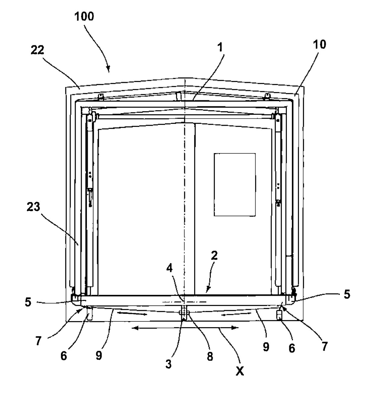
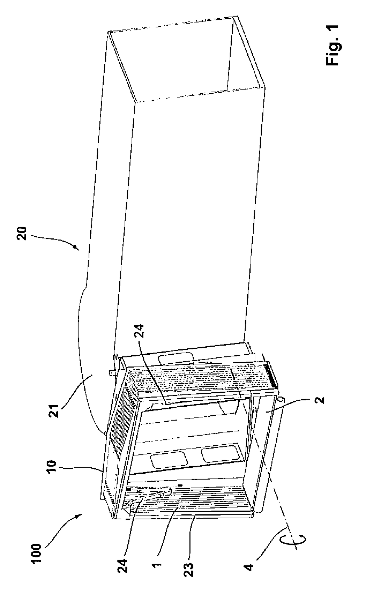
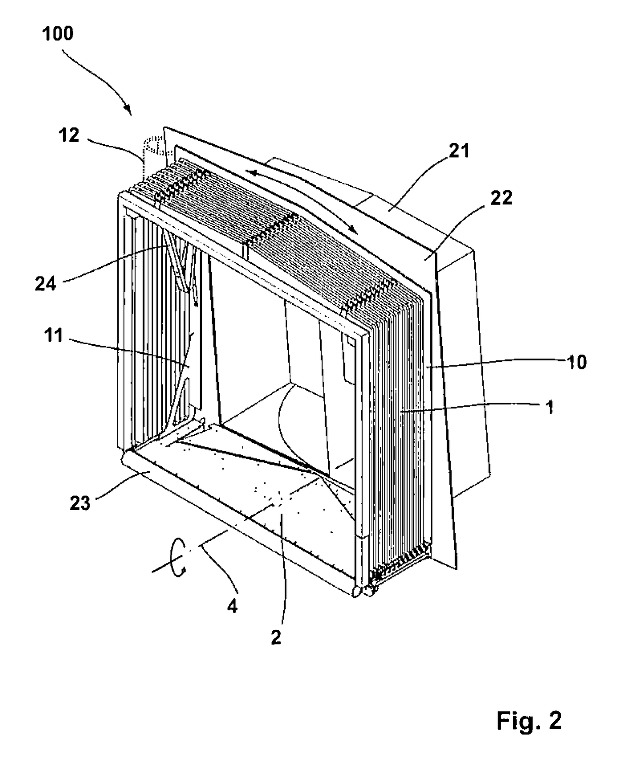
[0031]FIG. 1 shows a coupling module 100 in an arrangement at a passenger bridge 20. A cabin 21 that is a component of the passenger bridge 20 is arranged at a front end of the passenger bridge 20 facing the aircraft. The coupling module 100 is arranged pivotably about an imaginary horizontal pivot axis 4 at the cabin 21. The coupling module 100 has a frame at its free side that is arranged at a projecting roof 1 and that can be arranged to contact the outer skin of the aircraft and the frame is designed as a bumper 23. A respective articulated arm 24 is arranged at both sides in the interior of the coupling module 100 and serves to carry out of a deployment movement of the projecting roof 1 of the coupling module 100 to ultimately be able to place the bumper 23 at the outer skin of the aircraft body. The representation of the coupling module 100 furthermore shows the floor arrangement 2 which the passengers tread on directly after leaving the aircraft.

[0032]If the coupling module 1...


PUM


Abstract

A coupling module forms an interface between a cabin of a passenger bridge and an aircraft. The coupling module has a projecting roof and a floor arrangement overspanned by the projecting roof. The floor arrangement is pivotable about a horizontal pivot axis relative to the cabin. At least the floor arrangement and the projecting roof have a common pivot axis that is arranged in or beneath the floor arrangement, with the floor arrangement at least indirectly and substantially supporting the projecting roof.

Description

CROSS REFERENCE TO RELATED APPLICATIONS[0001]This application claims priority from European Application No. EP16196300.4 filed Oct. 28, 2016, the entire content of which is incorporated herein by reference.FIELD OF THE INVENTION[0002]The invention relates to a coupling module to form an interface between the cabin of a passenger bridge and an aircraft, wherein the coupling module has a projecting roof and a floor arrangement overspanned by the projecting roof and wherein the floor arrangement is pivotable about a horizontal pivot axis relative to the cabin.BACKGROUND OF THE INVENTION[0003]Passenger bridges are sufficiently known from the prior art. They serve the transition for persons from the aircraft directly into the airport building. Since the access to the airport building is frequently arranged higher than the door opening of the aircraft, the aircraft bridges, which are held by a traveling mechanism at the front, movable end, frequently extend at a downward slope in the dire...

Claims


Application Information

Patent Timeline
Patent Type & Authority Patents(United States)
IPC IPC(8): B64F1/305E01D15/00E01D18/00
CPCB64F1/3055E01D18/00E01D15/005B64F1/305
Inventor SCHUSTER, HEINZ
Owner HUBNER GMBH
Why Eureka
Try Eureka