Outer-rotor-type switched reluctance motor

a switched reluctance motor and outer-rotator technology, applied in the direction of synchronous motors, magnetic circuit rotating parts, magnetic circuit shape/form/construction, etc., can solve the problems of deteriorating the overall use efficiency of magnetic energy, difficult placement of excitation coil b>30/b> in a stable position, and too complicated coil winding work, etc., to achieve more hardness and durability, simplify the coil winding work, and slim down the effect of the effect o

Inactive Publication Date: 2018-11-27
SN INNOVATION
View PDF10 Cites 0 Cited by
  • Summary
  • Abstract
  • Description
  • Claims
  • Application Information

AI Technical Summary

Benefits of technology

[0010]Accordingly, an object of the present invention is to provide an outer-rotator-type switched reluctance motor that allows as short a magnetic path as possible, easier coil winding, a smaller size, and an optimized structure for outer-rotor-type motors.
[0021]According to the present invention configured as described above, since the coil 130 is wound to pass through the space between the upper and lower salient pole pieces 111 after forming slots 112 in the stator salient poles 110 in the circumferential direction, coil winding work may be simplified by performing coil winding along the outer circumferential surface of the stator core 100. No separate room is required for coil winding, thus sliming it down. A smaller number of parts are required, thus leading to more hardness and durability. By forming a magnetic circuit of a magnetic field created as the stator salient poles and the rotor salient poles circulate the coil, the magnetic path may be minimized, allowing for minimized magnetic loss and Eddy current loss.

Problems solved by technology

Thus, magnetic loss may arise in the section of magnetic paths formed in the circumferential direction, thus deteriorating the overall use efficiency of magnetic energy.
Further, since the excitation coil 30 is required to be wound around each stator salient pole 11, the coil winding work becomes too tricky, and the excitation coil 30 is difficult to place in a stable position.
Further, the need of an extra room for winding the coil renders it difficult to reduce the overall size of the motor.

Method used


Image

  • Outer-rotor-type switched reluctance motor
  • Outer-rotor-type switched reluctance motor
  • Outer-rotor-type switched reluctance motor

Examples


first embodiment

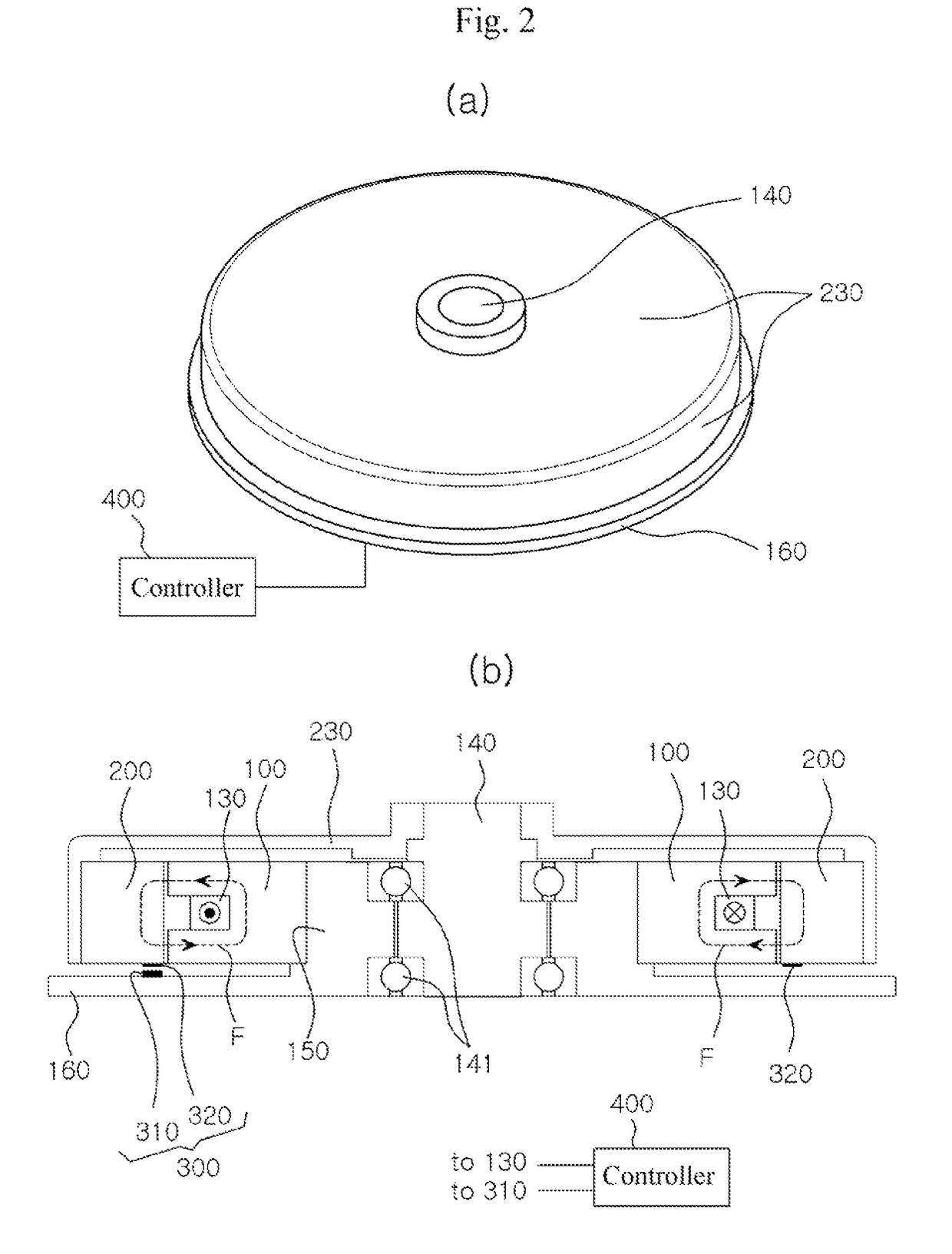
[0046]According to the present invention, the switched reluctance motor is of an outer rotor type and includes a stator core 100, a rotator core 200, a position detecting means 300, and a controller 400. According to the present invention as shown in FIGS. 2 to 5, the switched reluctance motor is a single-phase motor having a single coil 130 wound around the stator core 100.

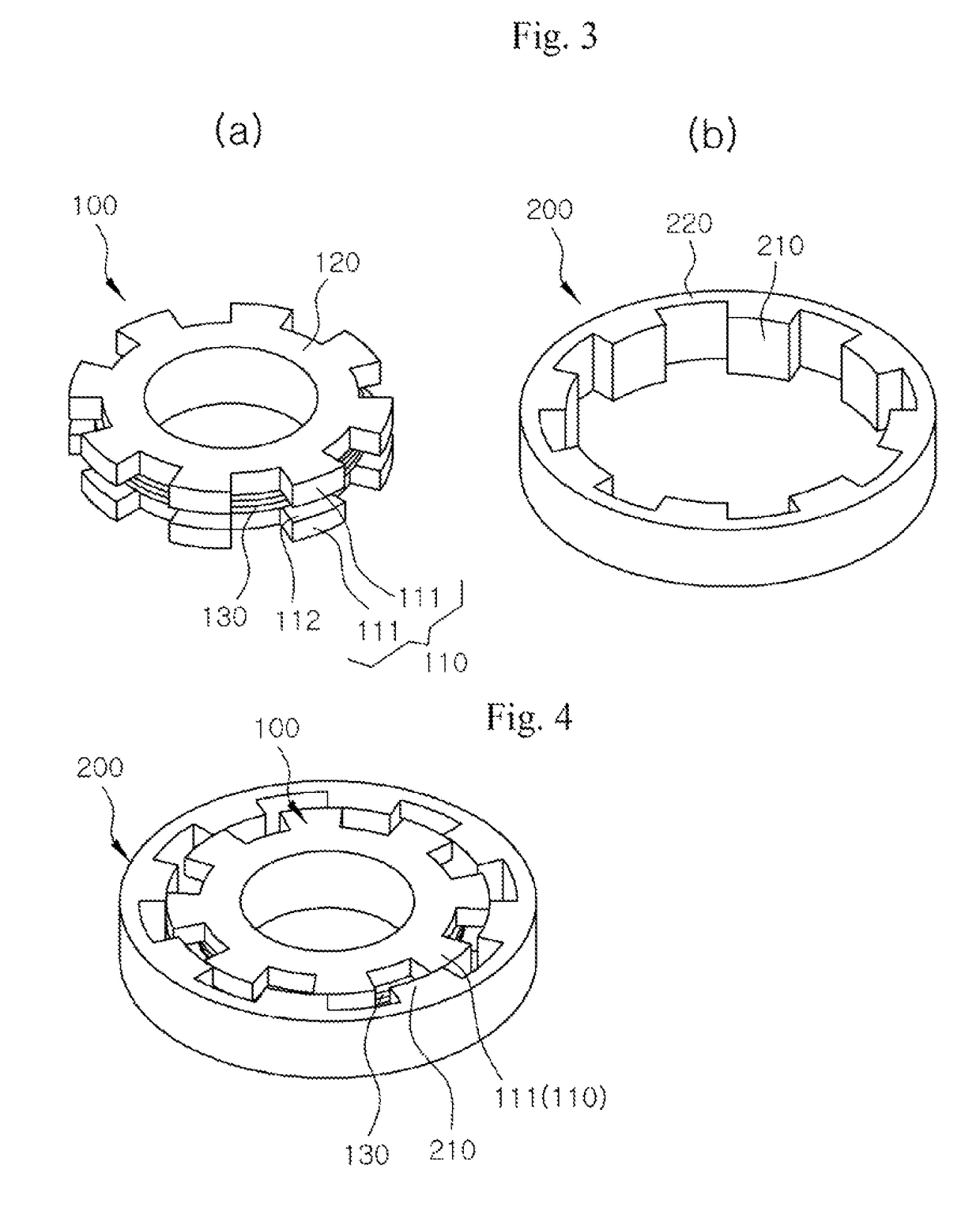
[0047]The stator core 100 includes a cylindrical stator yoke 120 having a center portion bored therethrough in upper and lower directions, a plurality of stator salient poles 110 formed isotropic-rectangularly on the outer circumferential surface of the stator yoke 120 (or at equidistant intervals along the circumferential direction), and a coil 130 receiving electricity to create a magnetic flux. In the embodiment shown in the drawings, the motor is an eight-pole motor having eight stator salient poles 110, and the rotator core described below also has eight rotor salient poles 210.

[0048]According to the present...

second embodiment

[0089]FIG. 6 illustrates a perspective view (a) of a stator core and a perspective view (b) of a rotator core among components of an outer-rotator-type switched reluctance motor according to the present invention. FIG. 7 is a plan view virtually illustrating changes in relative positions of stator cores 100 (100-1 and 100-2) and a rotor core 200 (200-1 and 200-2).

[0090]Referring to FIGS. 6 and 7, the stator core 100 includes a first stator core 100-1, a second stator core 100-2 stacked on the first stator core 100-1, with an annular magnetic insulator 170 disposed therebetween. The stator salient poles of the first stator core 100-1 and the stator salient poles of the second stator core 100-2 are placed along vertical lines.

[0091]The rotator core 200 includes a first rotator core 200-1 surrounding the first stator core 100-1 with an interval disposed therebetween and a second rotator core 200-2 surrounding the second stator core 100-2 with an interval disposed therebetween and stack...

third embodiment

[0094]FIG. 8 illustrates a perspective view (a) of a stator core and a perspective view (b) of a rotator core among components of an outer-rotator-type switched reluctance motor according to the present invention.

[0095]According to the third embodiment of the present invention, the stator core 100 includes three stator cores 100-1, 100-2, and 100-3 stacked one over another and annular magnetic insulators 170 arranged between the three stator cores 100-1, 100-2, and 100-3. The stator salient poles 110 form eight rows of salient poles on the outer circumferential surface thereof and aligned in line along the rotation shaft direction. That is, an eight-pole structure is formed.

[0096]The rotator core 200 has also such a structure in which three rotator cores 200-1, 200-2, and 200-3 respectively corresponding to the three stator cores 100-1, 100-2, and 100-3 are stacked one over another with annular magnetic insulators 240 disposed therebetween. Rotor salient poles 210-1, 210-2, and 210-...


PUM


Abstract

The present invention relates to an outer-rotator-type switched reluctance motor that may provide a shortest magnetic path by configuring a magnetic circuit in stator salient poles and rotor salient poles with circumferential-directional slots formed in the stator salient poles and coils passing through the slots and wound along the circumferential direction of the stator core, may thus minimize magnetic loss in the cores to maximize use efficiency of magnetic energy, and may provide a sturdy structure while simplifying coil winding work.

Description

TECHNICAL FIELD[0001]The present invention relates to an outer-rotator-type switched reluctance motor configured with a stator core having stator salient poles formed on an outer circumferential surface thereof and excited by a coil and an outer rotor core having rotor salient poles formed on an inner circumferential surface thereof and facing the stator salient poles with air gaps disposed between the stator salient poles and the rotor salient poles, and more specifically, which may thus minimize magnetic loss in the cores to maximize use efficiency of magnetic energy, and may provide a sturdy structure while simplifying coil winding work.DISCUSSION OF RELATED ART[0002]A switched reluctance motor (SRM) has a simplified structure without the need of a brush, in which an excitation coil is wound only on the stator and the rotator is constituted only of an iron core without any excitation means (e.g., an excitation coil or permanent magnet). Switched reluctance motors are easy to manu...

Claims


Application Information

Patent Timeline
Patent Type & Authority Patents(United States)
IPC IPC(8): H02K1/08H02K19/10H02K11/00H02K3/48H02K15/00H02K3/52H02K3/38H02K1/24H02K1/16H02K37/04H02K11/215H02K1/14
CPCH02K1/246H02K1/08H02K1/145H02K1/16H02K1/24H02K3/48H02K11/00H02K11/215H02K15/0031H02K19/10H02K37/04H02K3/52H02K2213/03
Inventor JEUNG, YOUNG CHUN
Owner SN INNOVATION
Why Eureka
Try Eureka