Sight system for projectile-launching devices

a projectile-launching device and projectile-launching technology, applied in the field of sight, can solve the problems of difficulty in seeing targets, eye focus, and very simple bow, and achieve the effect of improving accuracy

Active Publication Date: 2018-12-11
HOLLARS ANTHONY
View PDF10 Cites 4 Cited by
  • Summary
  • Abstract
  • Description
  • Claims
  • Application Information

AI Technical Summary

Benefits of technology

[0014]The present invention features an archery sight system that is adjustable for distance of a target along an arc that always aligns a sight line perfectly with an archer's eye so that use of any type of sight is allowable without moving the correct draw position and nock point allowing for better accuracy.

Problems solved by technology

Sights for accurately placing a projectile (such as an arrow) into a target have evolved from ones using instinct and practice to very complex mechanical devices.
For example, in primitive archery, a bow was very simple and had a limited effective range.
Without wishing to limit the present invention to any theory or mechanism, it is believed that the configuration with the peep sight woven into the bowstring may present challenges, for example the small aperture may cause difficulty in seeing targets in low-light settings.
And, it may cause the eye to have to focus at three ranges: just in front of the eyeball, at the front sight, and at the target some yards away.
The use of multiple reference points may lead to inaccuracies (e.g., one or more of the reference points end up out of focus).
While these may be effective for a single range or narrow set of distances, they may present challenges because of the large movement of the sight required to compensate for the trajectory of an arrow.
With this type of sight, the archer must move the shooting stance and anchor point of the bow at full draw, which can result in inaccuracy.
These often do not provide the alignment of the sight line to the archers eyeball over a large range of distance settings.
They can be used in one narrow range such as a target shooting at a specific yardage, but oftentimes these do not allow the sight to be used over a range of distances without the movement of the sight causing the misalignment of the sight line between the archers eye and the target so significantly that the archers anchor point at full draw and stance are greatly affected compromising accuracy (e.g., Messer Optics,™ Opti-Mount™).
Note that other sights do not allow a perfect alignment with the archer's eye throughout the range of the bow; they cause the archer to move the bow substantially from the proper shooting position and anchor point during full draw to align the sight with the target.

Method used


Image

  • Sight system for projectile-launching devices
  • Sight system for projectile-launching devices
  • Sight system for projectile-launching devices

Examples


Embodiment Construction

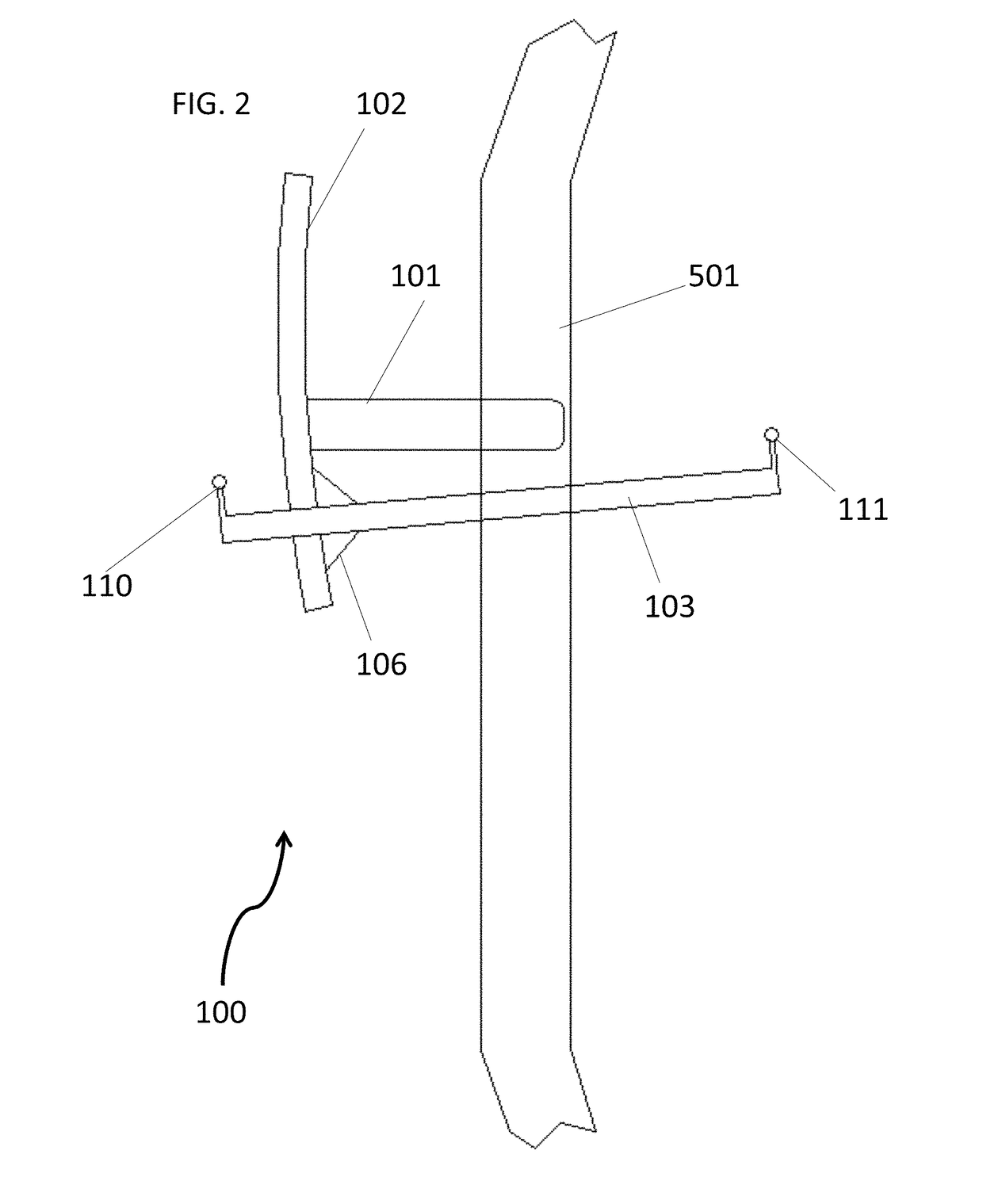
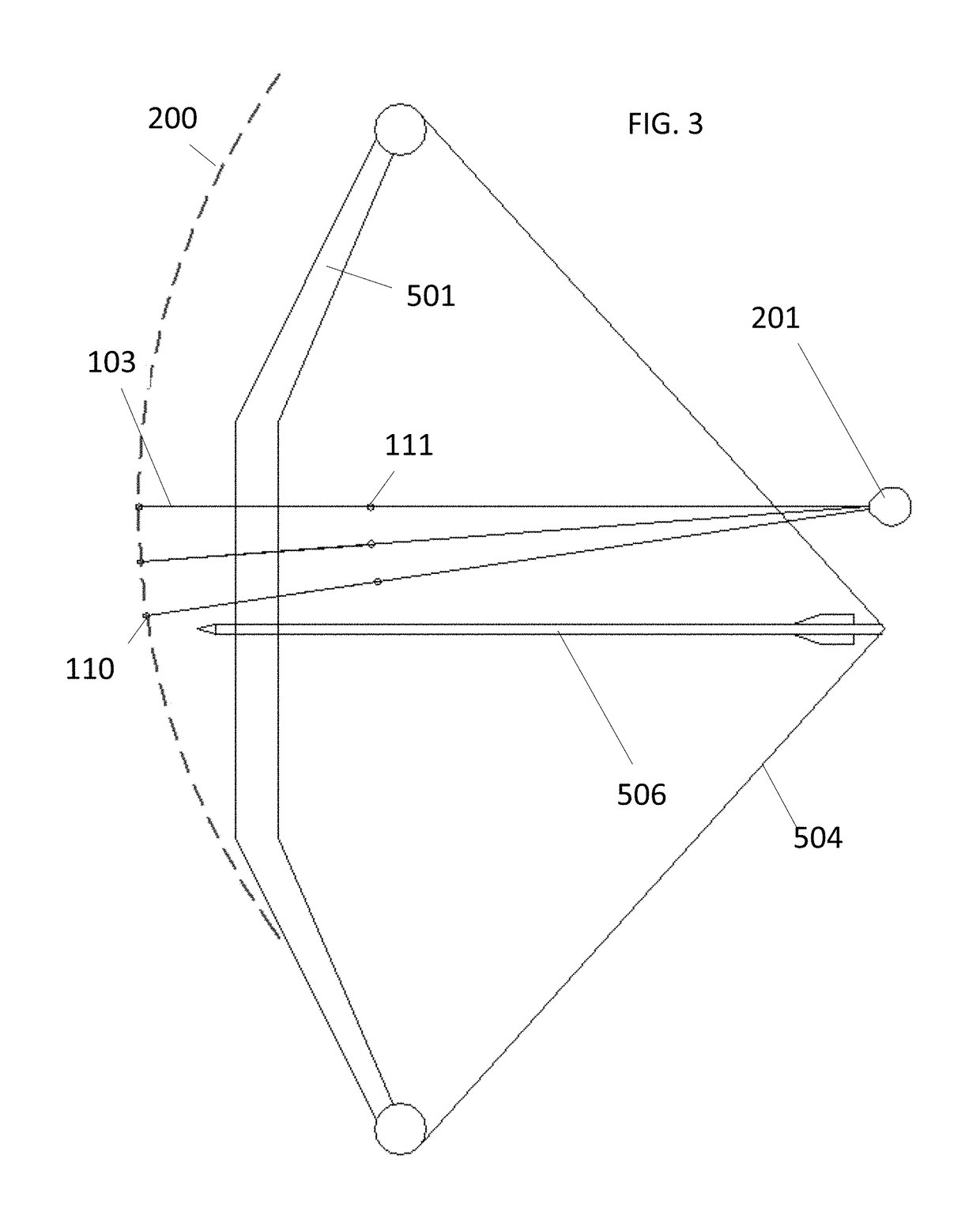
[0028]Following is a list of elements corresponding to a particular element referred to herein:[0029]100 sight system[0030]101 mount assembly[0031]102 arc track[0032]103 sight line support[0033]106 attachment[0034]110 front sight[0035]111 rear sight[0036]201 eyeball[0037]501 bow handle[0038]504 bowstring[0039]506 arrow[0040]512 target

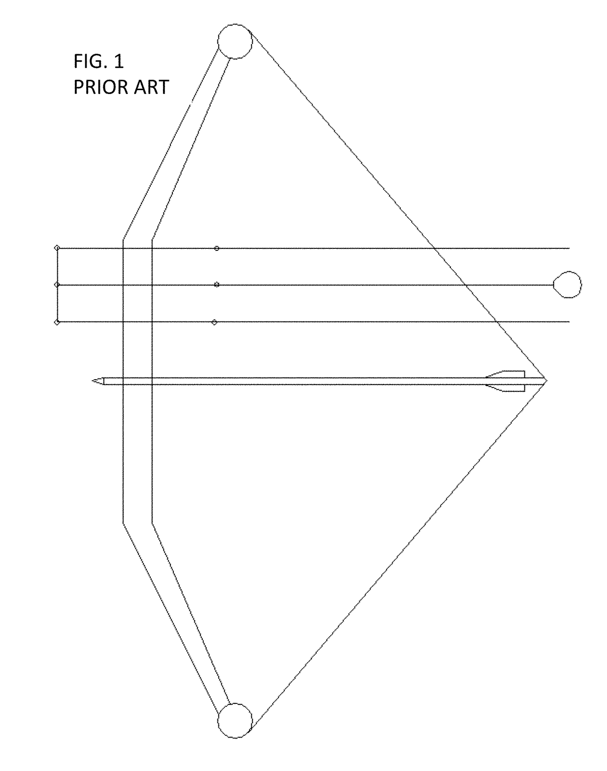
[0041]Referring now to FIGS. 2-6, the present invention features a sight system (100) for bows, crossbows, or other projectile-launching devices. The sight system (100) of the present invention allows for accurate alignment of an arrow for reaching a target. For reference, FIG. 5 shows a line of sight extending from the eyeball (201) of an archer to a target (512) with the arrow (506) in position as shown.

[0042]The sight system (100) of the present invention comprises a mount assembly (101) having a proximal end that is attached or can be attached to a bow (501) or other appropriate component and a distal end (the distal end being opposite the proximal ...


PUM


Abstract

An archery sight with a sight line that is capable of movement on an arced path along a radius that approximates the distance between an archer's eyeball and the sight. The arc is the part of the radius that includes the portion needed to position the sight accurately to compensate for an arrow's trajectory from the shortest to longest range that the bow is capable of. This results in a sight line that always aligns perfectly with an archer's eye.

Description

CROSS REFERENCE[0001]This application claims priority to U.S. Provisional Patent Application No. 62 / 100,363 filed Jan. 6, 2015, the specification of which is incorporated herein in its entirety by reference.FIELD OF THE INVENTION[0002]The present invention relates to sights for bows and crossbows and other similar projectile-launching devices or the like.BACKGROUND OF THE INVENTION[0003]Sights for accurately placing a projectile (such as an arrow) into a target have evolved from ones using instinct and practice to very complex mechanical devices. For example, in primitive archery, a bow was very simple and had a limited effective range. The use of a device to aim the bow was not needed. As materials and design became better and bows became capable of much faster arrow speeds and range, sighting devices became popular. Prior art sights share come common features: they have a rear peep sight mounted in the bowstring or a rear sight mounted to the bow, and they use these rear sights to...

Claims


Application Information

Patent Timeline
Patent Type & Authority Patents(United States)
IPC IPC(8): F41G1/467
CPCF41G1/467
Inventor HOLLARS, ANTHONY
Owner HOLLARS ANTHONY
Why Eureka
Try Eureka