Stimulation device adapter

a technology of a stimulation device and a plug-in, which is applied in the direction of osteosynthesis devices, artificial respiration, therapy, etc., can solve the problems of nerve damage, nerve bruises, stretched or even severed nerves, and surgical procedures are not risk-free, and achieve accurate evaluation of the neuromuscular system.

Active Publication Date: 2018-12-18
CHECKPOINT SURGICAL
View PDF126 Cites 10 Cited by
  • Summary
  • Abstract
  • Description
  • Claims
  • Application Information

AI Technical Summary

Benefits of technology

[0011]Additional aspects of the invention provide a tissue stimulation system that may be sterilized using ethylene oxide, for example, and prepackaged for single use. The stimulation signal of the tissue stimulation system includes an amplitude that may range between about zero milliamps and about 20 milliamps, allowing for accurate selective stimulation of both muscles and nerves, and also identification of nerves and muscles, muscle attachments, or to contract muscles to assess the quality of surgical interventions. The tissue stimulation signal duration may include a range between about zero microseconds and about 200 microseconds, for example. The first indication provided by the tissue stimulation system may include, for example, audio and visual indications. The tissue stimulation system may further include a second indication means to provide confirmation of power on to the device and delivery of a stimulation signal to the electrically conductive surface. The first and second indication means may be combined into a single indication means. The operative element of the tissue stimulation system may comprise a probe, for example, where the electrically conductive surface of the probe comprises between about 1 millimeter and about 10 millimeters of the proximal end of the probe, and the probe comprises a diameter between about 0.5 millimeters and about 1.5 millimeters. The tissue stimulation system may also further include a return electrode electrically coupled to the stimulation control device.
[0023]The devices, systems, and methods are well suited, e.g., for differentiating and / or identifying localized branches of the vagus nerve. The vagus nerve runs from the brain through the face and thorax to the abdomen. It is a mixed nerve that contains parasympathetic fibers. The vagus nerve has the most extensive distribution of the cranial nerves. Its pharyngeal and laryngeal branches transmit motor impulses to the pharynx and larynx; its cardiac branches act to slow the rate of heartbeat; its bronchial branch acts to constrict the bronchi; and its esophageal branches control involuntary muscles in the esophagus, stomach, gallbladder, pancreas, and small intestine, stimulating peristalsis and gastrointestinal secretions. Being able to differentiate and / or identify the presence of a branch of the vagus nerve within a given tissue region within the body makes possible the development and application of diverse diagnostic and / or therapeutic techniques for parasympathetic mediation of a diverse number of anatomic functions, e.g., in the digestive system, the respiratory system, or the heart.
[0024]For example, one aspect of the invention provides devices, systems, and methods that make possible the differentiation and identification of the epicardial fat pads on the surface of the heart, which are innervated by parasympathetic vagal nerve fibers. The devices, systems, and methods thereby make it possible to access the parasympathetic nervous system of the heart for therapeutic benefits, such as to control the ventricular rate or to provide physiologic control of the AV nodal rate.

Problems solved by technology

Even with today's sophisticated medical devices, surgical procedures are not risk-free.
While these differences may be slight, if the surgeon fails to properly identify one or several nerves, the nerves may be bruised, stretched, or even severed during an operation.
The negative effects of nerve damage can range from lack of feeling on that part of the body to loss of muscle control.
Determining the extent of muscle and nerve injury is not always possible using visual inspection.

Method used


Image

  • Stimulation device adapter
  • Stimulation device adapter
  • Stimulation device adapter

Examples


Embodiment Construction

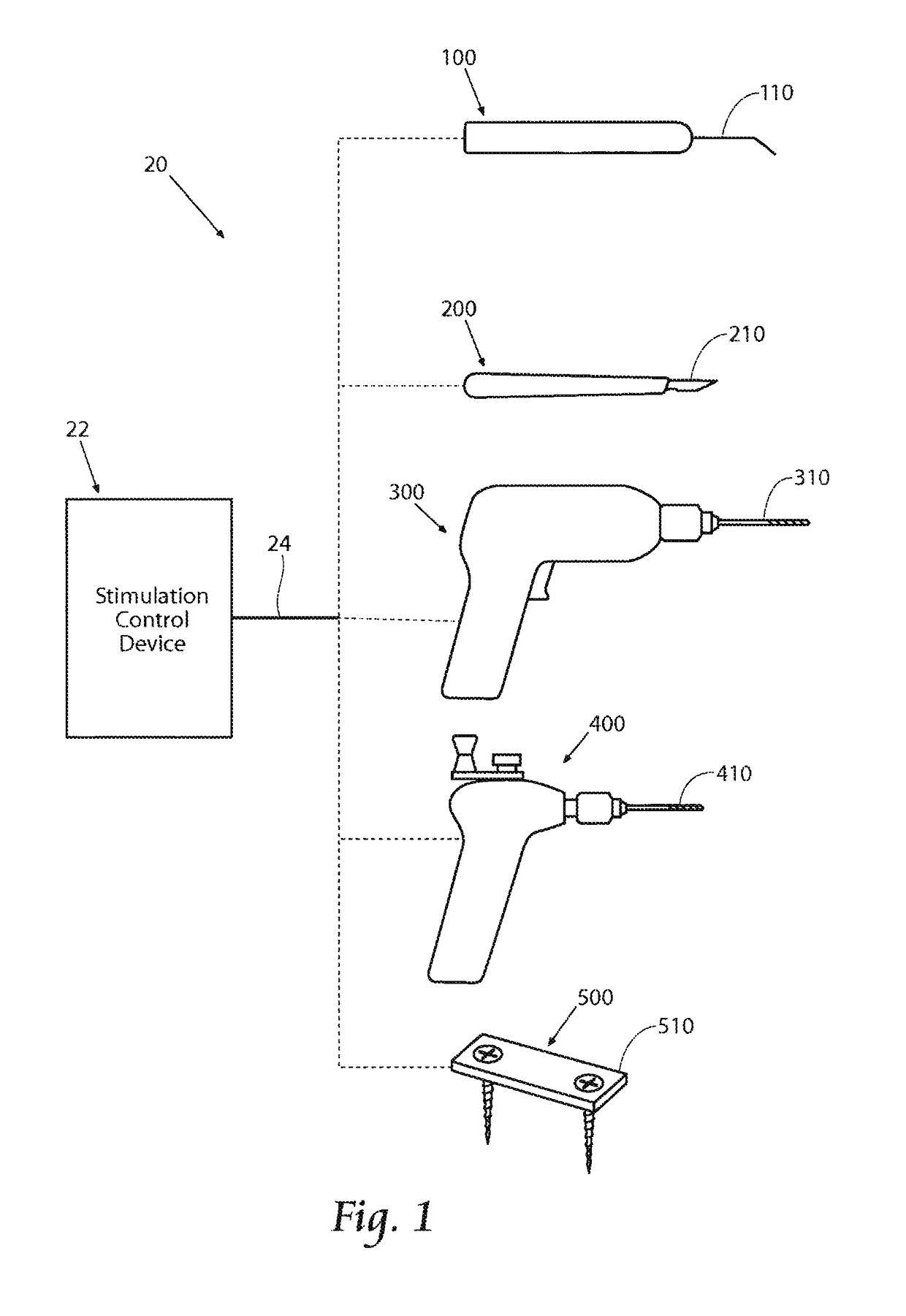
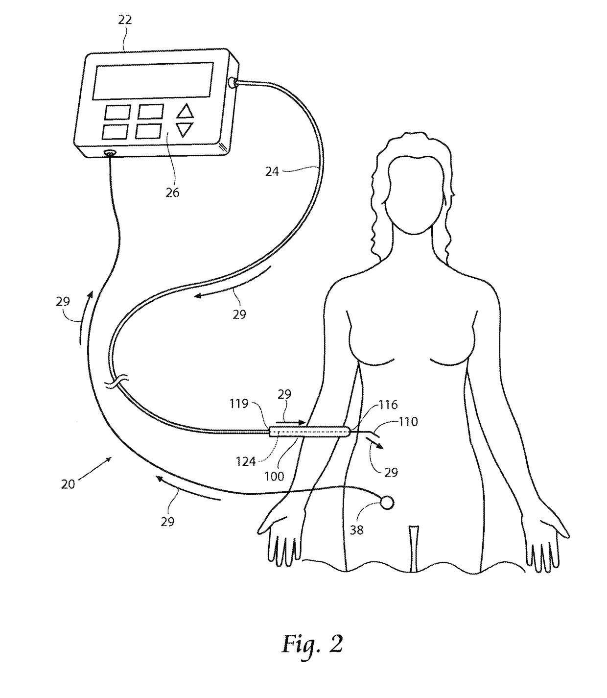
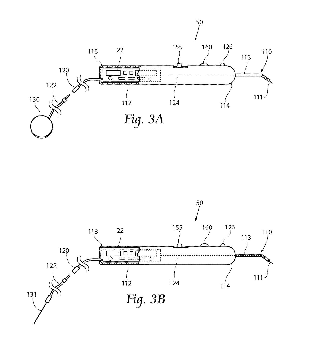
[0065]This Specification discloses various systems and methods for safeguarding against nerve, muscle, and tendon injury during surgical procedures or confirming the identity and / or location of nerves, muscles, and tendons and evaluating their function or the function of muscles enervated by those nerves. The systems and methods are particularly well suited for assisting surgeons in identification of nerves and muscles in order to assure nerve and muscle integrity during medical procedures using medical devices such as stimulation monitors, cutting, drilling, and screwing devices, pilot augers, and fixation devices. For this reason, the systems and methods will be described in the context of these medical devices.

[0066]The systems and methods desirably allow the application of a stimulation signal at sufficiently high levels for the purposes of locating, stimulating, and evaluating nerve or muscle, or both nerve and muscle integrity in numerous medical procedures, including, but not...


PUM


Abstract

A stimulation device includes an adapter component to increase the usability of the stimulation device. The adapter may be a bipolar adapter arranged to connect to the housing of the stimulation device. The adapter may include a clip having a first channel configured to receive an operative element therein and a second channel having a return operative element therein. The return operative element is in electrical communication with an electrical circuit of said stimulation control device. Alternatively, the adapter may be a percutaneous adapter comprising a connector configured to connect to an operative element of a stimulation device and a lead wire connected to the connector. A needle may be connected to the lead wire to deliver a electrical stimulation signal to a target tissue located beneath the skin of a subject patient.

Description

RELATED APPLICATIONS[0001]This application is a continuation-in-part of co-pending U.S. patent application Ser. No. 13 / 934,384 filed on Jul. 3, 2013 and entitled “Systems and Methods for Intra-Operative Stimulation,”, which is a continuation of co-pending U.S. patent application Ser. No. 13 / 466,485, filed Sep. 20, 2012, and entitled “Systems and Methods for Intra-Operative Stimulation,” which is a continuation of co-pending U.S. patent application Ser. No. 13 / 014,452, filed Jan. 26, 2011, and entitled “Systems and Methods for Intra-Operative Stimulation,” which is a continuation of co-pending U.S. patent application Ser. No. 11 / 651,165, filed Jan. 9, 2007, and entitled “Systems and Methods for Intra-Operative Stimulation,” which is a continuation-in-part of U.S. patent application Ser. No. 11 / 099,848, filed Apr. 6, 2005, and entitled “Systems and Methods for Intra-Operative Stimulation,” which claims the benefit of U.S. Provisional Patent Application Ser. No. 60 / 657,277, filed Mar. ...

Claims


Application Information

Patent Timeline
Patent Type & Authority Patents(United States)
IPC IPC(8): A61B5/04A61B50/30A61B17/16A61B17/88A61B17/00A61N1/36A61B5/00A61B5/113A61B90/00
CPCA61B5/04001A61B5/4887A61B5/4893A61B17/1626A61B17/8875A61B50/30A61N1/36014A61B5/1135A61B5/4519A61B90/04A61B2017/00022A61B2017/00154A61B5/24
Inventor SAKAI, JONATHANSTROTHER, ROBERT B.MRVA, JOSEPH J.THROPE, GEOFFREY B.
Owner CHECKPOINT SURGICAL
Why Eureka
Try Eureka