Image display device and driving method of the same

a technology of image display device and driving method, which is applied in the direction of instruments, static indicating devices, etc., can solve the problems of difficult to perform appropriate vsub>th/sub>compensation in every pixel, rapid progression of the changes of pixel luminance, etc., to improve the reliability of the pixel circuit and improve the image uniformity of the image display device.

Active Publication Date: 2018-12-25
LG DISPLAY CO LTD
View PDF31 Cites 0 Cited by
  • Summary
  • Abstract
  • Description
  • Claims
  • Application Information

AI Technical Summary

Benefits of technology

[0012]However, the Vth compensation is applied to a limited range, and Vth being out of the range results in rapid progression of the changes of pixel luminance due to Vth changes.
[0016]According to an image display device and a driving method of the same, it is possible to prevent the threshold voltage of the driving element from being out of the detection range, thereby improving the reliability of the pixel circuit.
[0017]According to an image display device and a driving method of the same, an amount of shift in a threshold voltage is equalized for each pixel and thus it is possible to improve image uniformity in the image display device.

Problems solved by technology

However, the Vth compensation is applied to a limited range, and Vth being out of the range results in rapid progression of the changes of pixel luminance due to Vth changes.
Even if the variation of Vth is within the compensation range, it is difficult to perform appropriate Vth compensation in every pixel because the progression of Vth shift differs from one pixel to another.

Method used


Image

  • Image display device and driving method of the same
  • Image display device and driving method of the same
  • Image display device and driving method of the same

Examples


Embodiment Construction

[0030]The present invention relates to an image display device and a driving method of the same.

[0031]Preferred embodiments of an image display device and a driving method of the same is explained in detail below with reference to the drawings. The present invention is not limited to the embodiments described below.

[0032]An image display device according to an embodiment includes a plurality of pixel circuits that are arranged in matrix and each pixel circuit includes an light-emitting element and a driving element.

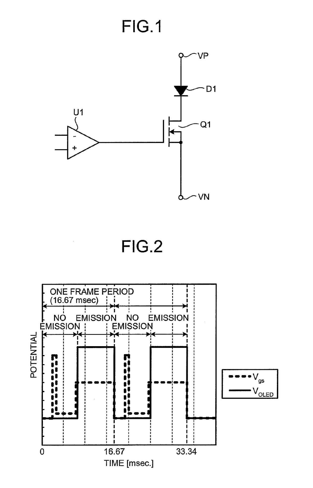
[0033]FIG. 1 shows a pixel circuit corresponding to a single pixel in an image display device according to a preferred embodiment of the present invention. To facilitate understanding of operations of a driving element Q1, the pixel circuit shown in FIG. 1 is simplified.

[0034]The pixel circuit shown in FIG. 1 includes a light-emitting element D1, the driving element Q1 that is connected to the light-emitting element D1 in series, and a controller U1 that controls the driv...


PUM


Abstract

An image display device including a light-emitting element configured to emit light corresponding to a current flowing therethrough; a driving element that is connected to the light-emitting element and configured to control light emission of the light-emitting element; and a control unit configured to apply a reverse bias voltage to a first n-type driving element whose the threshold voltage determined at a specific time is equal to or higher than a positive predetermined voltage level for shifting the threshold voltage of the first n-type driving element in a negative direction, and not apply the reverse bias voltage to a second n-type driving element whose the threshold voltage determined at the specific time is lower than the positive predetermined voltage level for shifting the threshold voltage of the second n-type driving element in a positive direction when the light-emitting element does not emit light.

Description

CROSS-REFERENCE TO RELATED APPLICATIONS[0001]This application is a Continuation of co-pending U.S. application Ser. No. 12 / 597,884 filed on Jan. 25, 2010, which is the National Phase of PCT / JP2008 / 056135 filed on Mar. 28, 2008, which claims priority under 35 U.S.C. 119(a) to Application No. 2007-119010, filed on Apr. 27, 2007, in Japan. The contents of all of these applications are hereby incorporated by reference as fully set forth herein in their entirety.BACKGROUND OF THE INVENTION[0002]Field of the Invention[0003]The present invention relates to an image display device and a driving method of the same.[0004]Discussion of the Related Art[0005]Recently, image display and illumination devices using electroluminescence light-emitting elements (hereinafter, referred to as “light-emitting elements”) have attracted many scientists.[0006]In particular, image display devices are made up of a plurality of pixels each including a light-emitting element that emits light corresponding to a p...

Claims


Application Information

Patent Timeline
Patent Type & Authority Patents(United States)
IPC IPC(8): G09G3/32G09G3/3233
CPCG09G3/32G09G3/3233G09G2300/043G09G2320/043G09G2310/0256G09G2310/0275G09G2320/0233G09G2300/0842G09G3/20G09G3/30
Inventor TAKASUGI, SHINJIHASUMI, TARO
Owner LG DISPLAY CO LTD
Why Eureka
Try Eureka