Air-conditioning apparatus

a technology of air-conditioning apparatus and compressor, which is applied in the direction of lighting and heating apparatus, refrigeration components, heating types, etc., can solve the problems of inability to exert the required heating capacity, and inability to increase the frequency of the compressor, so as to prevent excessive discharge temperature of the compressor, prolong the life of the compressor, and prevent damage to the compressor

Active Publication Date: 2019-01-01
MITSUBISHI ELECTRIC CORP
View PDF32 Cites 0 Cited by
  • Summary
  • Abstract
  • Description
  • Claims
  • Application Information

AI Technical Summary

Benefits of technology

[0014]The air-conditioning apparatus according to the one embodiment of the present invention is capable of preventing excessive increase in discharge temperature of the compressor in both of the cooling operation and the heating operation. Thus, according to the air-conditioning apparatus of the one embodiment of the present invention, it is possible to prevent damage to the compressor, extend the life of the compressor, and to exert required heating capacity in the heating operation under low outside air temperature.

Problems solved by technology

When an air-conditioning apparatus such as a multi-air-conditioning apparatus for a building performs a heating operation under low outside air temperature, a discharge temperature of a compressor is excessively high, and hence a frequency of the compressor cannot be increased, with the result that required heating capacity cannot be exerted.
Further, when a refrigerant such as R32 is used, the discharge temperature of the compressor is excessively high even during a cooling operation under low outside air temperature.

Method used


Image

  • Air-conditioning apparatus
  • Air-conditioning apparatus
  • Air-conditioning apparatus

Examples


Embodiment Construction

[0022]Now, an embodiment of the present invention is described referring to the drawings. Note that, in the drawings referred to below including FIG. 1, the size relationship between components may be different from the reality in some cases. Further, in the drawings referred to below including FIG. 1, the same or corresponding parts are represented by the same reference symbols, and the same applies hereinafter. Further, the forms of the constituent elements described herein are only examples and the present invention is not limited to the forms described.

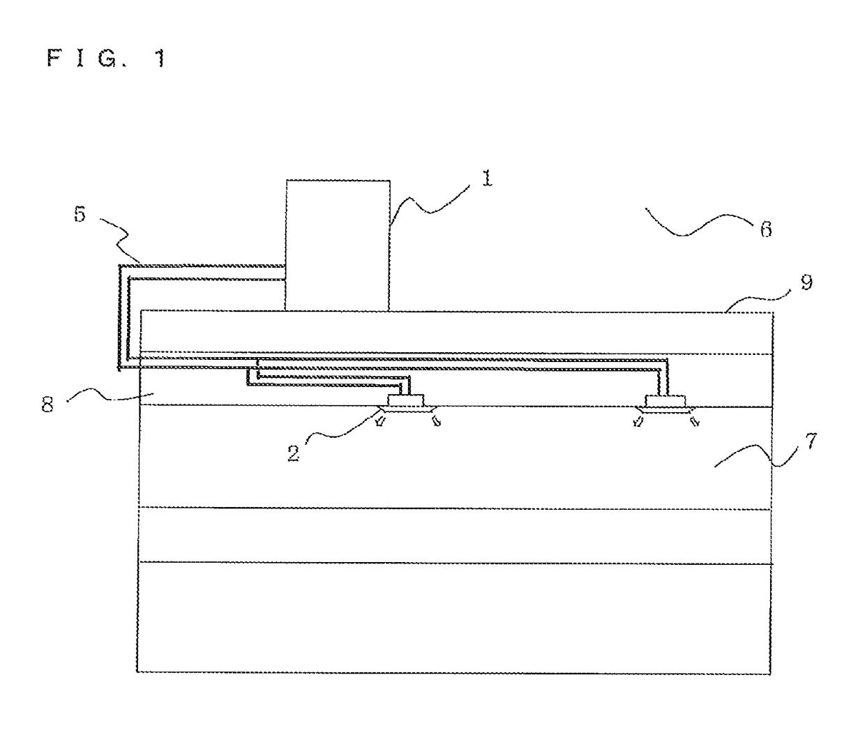
[0023]FIG. 1 is a schematic diagram illustrating an example of installation of an air-conditioning apparatus according to an embodiment of the present invention. Referring to FIG. 1, the example of installation of the air-conditioning apparatus is described. This air-conditioning apparatus is capable of selecting any one of a cooling mode and a heating mode as an operation mode by utilizing a refrigeration cycle for circulating re...


PUM


Abstract

An air-conditioning apparatus includes: a first bypass pipe connected to an inlet-side passage of an accumulator through a second expansion device, a second passage of a subcooling heat exchanger for exchanging heat between refrigerant flowing through the second passage of the subcooling heat exchanger and refrigerant flowing through a first passage of the subcooling heat exchanger, and a first opening and closing device; a second bypass pipe branched from the first bypass pipe between the subcooling heat exchanger and the first opening and closing device and connected to an injection port of a compressor through a second opening and closing device; and a third bypass pipe branched from a refrigerant pipe between a heat source-side heat exchanger and a use-side heat exchanger and connected to a refrigerant pipe between an inlet side of the compressor and an outlet side of the accumulator through a third expansion device.

Description

CROSS REFERENCE TO RELATED APPLICATION[0001]This application is a U.S. national stage application of International Application No. PCT / JP2013 / 056714 filed on Mar. 12, 2013, the disclosure of which is incorporated by reference.TECHNICAL FIELD[0002]The present invention relates to an air-conditioning apparatus to be applied to, for example, a multi-air-conditioning apparatus for a building.BACKGROUND ART[0003]When an air-conditioning apparatus such as a multi-air-conditioning apparatus for a building performs a heating operation under low outside air temperature, a discharge temperature of a compressor is excessively high, and hence a frequency of the compressor cannot be increased, with the result that required heating capacity cannot be exerted. Further, when a refrigerant such as R32 is used, the discharge temperature of the compressor is excessively high even during a cooling operation under low outside air temperature. Therefore, it is necessary to lower the discharge temperature...

Claims


Application Information

Patent Timeline
Patent Type & Authority Patents(United States)
IPC IPC(8): F25B41/00F24F11/83F25B40/00F24F5/00F25B1/10F25B13/00
CPCF24F11/83F25B1/10F25B13/00F25B40/00F24F5/001F25B2700/21152F25B2313/006F25B2313/02741F25B2313/0314F25B2400/13F25B2600/2501F25B2600/2509F25B2700/1931F25B2700/1933F25B2700/2101F24F11/84
Inventor YAMASHITA, KOJI
Owner MITSUBISHI ELECTRIC CORP
Why Eureka
Try Eureka