Roller with internal assembly

a technology of internal assembly and roller, which is applied in the direction of conveyors, rollerways, conveyor parts, etc., can solve the problems of material fatigue, wear and tear, and discrepancy between the orientation of the bearing assembly and the orientation of the internal assembly, so as to prevent excessive acceleration of goods

Active Publication Date: 2019-01-08
INTERROLL HLDG
View PDF15 Cites 7 Cited by
  • Summary
  • Abstract
  • Description
  • Claims
  • Application Information

AI Technical Summary

Benefits of technology

[0012]Both the bearing assembly and the internal assembly are supported on the rod as separate assemblies. In contrast to the roller with eddy current brake as the internal assembly described at the outset, the internal assembly and the bearing assembly of the roller according to the first aspect are formed as respective independent components, which are not firmly bonded. However, the internal assembly and the bearing assembly may be coupled with each other by positive engagement such that a transfer of force from the internal assembly to the roller shell and / or vice versa is enabled. The internal assembly may be tilted relative to the bearing assembly without interrupting and / or weakening the force coupling of the internal assembly to the bearing assembly.
[0039]A second aspect relates to a conveyor system with a stationary frame, in which a roller according to the first aspect is arranged, wherein the rod of the roller is fixed stationarily to the frame. Here, the conveyor system can in particular be formed as a non-driven conveyor system having a slope and at least one braked roller, which prevents excessive acceleration of the goods on the conveyor line. The internal assembly of the roller provides the braking effect required for this purpose, for example when the internal assembly is formed as a brake, in particular as an eddy current brake.

Problems solved by technology

This may lead to wear and tear as well as to material fatigue in such rollers having internal assemblies.
This results in a discrepancy between the orientation of the bearing assembly and the orientation of the internal assembly.
Furthermore, higher loads on the roller, such as the transport of heavy goods, or material fatigue depending on the age of the roller can lead to a change of this relative mutual orientation.
Especially at the eddy current sensor do high stresses occur during operation due to the braking effect between the magnet and the eddy current sensor on the one hand, and the force coupling of the eddy current sensor via the bearing assembly to the roller shell on the other hand.

Method used


Image

  • Roller with internal assembly
  • Roller with internal assembly
  • Roller with internal assembly

Examples


Embodiment Construction

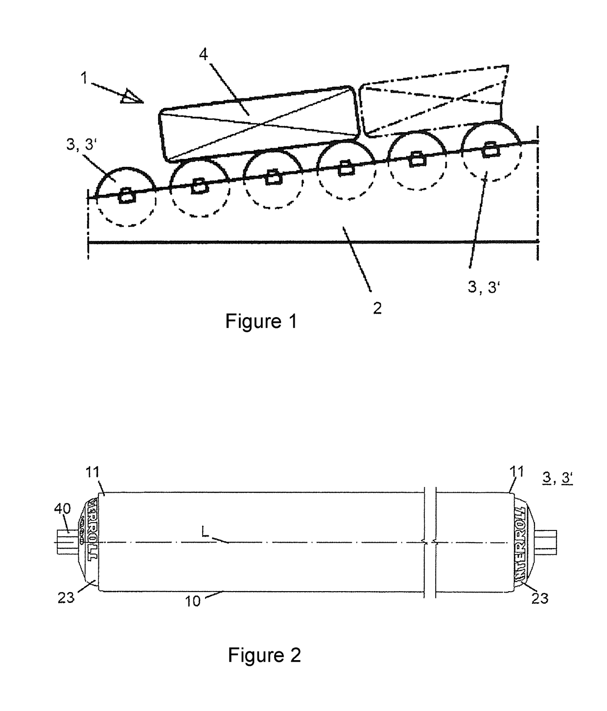
[0051]FIG. 1 shows a side view of a conveyor system 1 formed as a roller conveyor. The conveyor system 1 comprises a frame 2, which is arranged in a stationary way and on which a plurality of rollers 3; 3′ is arranged. The roller shells of the plurality of rollers 3; 3′ form a conveyor line for an item 4 being conveyed on the conveyor system 1. The rollers 3; 3′ may be formed to be free and without their own drive and / or their own brake, and carry the item 4 placed thereon in a supporting way, said item rolling down the conveyor line formed by the rollers 3; 3′ due to its weight. One or more of the rollers 3; 3′ can be formed as a roller having an internal assembly.

[0052]FIG. 2 is a side view of a roller 3; 3′ from a viewpoint radially spaced from the roller 3; 3′. The roller 3; 3′ is substantially cylindrical and extends in the longitudinal direction, i.e. along a longitudinal axis L of the roller 3; 3′. The roller 3; 3′ can be fixed to the frame 2 shown in FIG. 1 via a rod 40. The...


PUM


Abstract

A roller (3; 3′) has a stationary rod (40) arranged along a longitudinal axis (L) and a tubular roller shell (10) arranged around the rod (40). At least one bearing assembly (20; 20′) is arranged on the rod (40) so that the roller shell (10) can rotate about the longitudinal axis (L) of the roller (3; 3′). An internal assembly (30; 30′) is on the rod (40) within the roller shell (10) and is coupled to the roller shell (10) via the bearing assembly (20; 20′). Thus, upon rotation of the roller shell (10), an exchange of force occurs between the internal assembly (30; 30′) and the roller shell (10). The internal assembly (30; 30′) is coupled to the bearing assembly (20; 20′) by an end (31) that faces the bearing assembly (20; 20′) so that the internal assembly (30; 30′) can tilt relative to the bearing assembly (20; 20′).

Description

BACKGROUND1. Field of the Invention[0001]The invention relates to a roller having an internal assembly, and to a conveyor system.2. Description of the Related Art[0002]Conveyor systems regularly have frames on which wheels serving for transporting goods are attached. Here, goods can be transported on the rotating rollers.[0003]In order to influence the transport of goods on the conveyor system, some or all of the rollers may be equipped with a brake and / or a drive in the roller interior. Such an internal assembly arranged in the interior of the roller serves for force transmission to the roller shell of the roller to influence the rotational speed of the roller about its own longitudinal axis.[0004]DE 10 2012 003 499 A1 discloses a roller with an eddy current brake as an internal assembly is known. The eddy current brake arranged in the interior of the roller shell is pressed together with the roller bottom at a longitudinal end of the roller, via which bottom force transmission fro...

Claims


Application Information

Patent Timeline
Patent Type & Authority Patents(United States)
IPC IPC(8): B65G13/075B65G39/09B65G23/08
CPCB65G13/075B65G39/09B65G23/08
Inventor DUDEK, SIEGMUND
Owner INTERROLL HLDG
Why Eureka
Try Eureka