
Wind turbine with a wind sensing apparatus

a wind turbine and wind sensing technology, applied in the direction of wind turbines, engine control, wind energy generation, etc., can solve the problems of affecting the performance of wind turbines, affecting the success of measurements, and affecting the structural load of wind turbines and their components, so as to achieve easy installation and maintenance, and the effect of reducing the area and direction

Active Publication Date: 2019-01-08
GE RENEWABLE TECH WIND BV
View PDF10 Cites 0 Cited by
  • Summary
  • Abstract
  • Description
  • Claims
  • Application Information

AI Technical Summary

Benefits of technology

[0014]In this aspect, the wind sensing apparatus may be more easily accessible for maintenance than in prior art solutions. Particularly in offshore applications, no separate structures would be needed for housing or supporting wind sensing apparatus and additionally the accuracy of wind measurements may be improved compared to some prior art systems. Furthermore, if placed low enough, the blades will not affect the measurements either.
[0018]By positioning the remote wind sensing apparatus substantially near the base of the tower, the accuracy of the measurements of the remote wind sensing apparatus will not be affected by the bending moments and swaying experienced by the upper portion of the tower under strong winds. Furthermore, mounting and maintaining the remote wind sensing apparatus at the base of the tower is easier than doing so on the nacelle or on the hub.
[0019]In most embodiments, the wind turbine may comprise one or more mechanisms for moving the wind sensing apparatus along a surface of the support structure, i.e. the wind sensing apparatus may be moveable along a horizontal and a vertical axis of the support structure. Furthermore the wind sensing apparatus may comprise a pan-and-tilt scanning capability, i.e. from any point along the surface of the support structure the wind sensing apparatus may be further rotatable around its own horizontal and vertical axis to further broaden the areas and directions around the wind turbine in which wind speed and wind turbulence may be measured.
[0020]In some embodiments, the wind turbine may be located offshore. An aspect of having the wind sensing apparatus mounted to the support structure is that there is no requirement for an additional costly marine platform which makes the remote wind sensing apparatus equally easy to install and maintain inland as it is offshore.
[0023]Thereby, the remote wind sensing apparatuses on one or more wind turbines may be managed to measure wind speed and wind fluctuations in multiple directions and, hence, provide a detailed interpretation of wind evolution and the transverse structure of gusts of wind around the wind turbines.

Problems solved by technology

The performance of wind turbines is affected by turbulent wind conditions that cause structural loads on the wind turbine and its components.
However, the restricted field of view caused by the rotating blades of the turbine results in only approximately 75% of measurements being successful, with the laser beam striking a blade in the remaining 25% of cases.
Mounting the LIDAR on the hub overcomes the restricted field of view of nacelle mounted LIDAR systems, however its installation and maintenance is difficult due the height of the tower and the rotation of the hub.
The accuracy of the measurements taken by remote wind sensing apparatuses mounted on the nacelle or on the hub is furthermore affected by the bending moments and swaying experienced by the wind tower in strong winds.
SODARs are less likely to be mounted on the nacelle or the hub because the noises generated at the nacelle and / or at the hub interfere with the SODAR's sonic signals.
Although this solution is easily implemented inland, it is very costly to implement offshore as it would require building a separate offshore platform to carry the remote wind sensing apparatus.
In general, it is known that the turbulent movements in the wind will evolve between the time they are measured and when they reach the turbine, causing errors in the preview wind measurements.
In addition, the rotor blades have the effect of slowing down the mean velocity of the incoming wind near the rotor and further altering the turbulence characteristics.
A full and detailed interpretation of these events is difficult since the wind field is currently being probed only along a single line, and hence no information can be obtained on the transverse structure of the gusts.

Method used


Image

  • Wind turbine with a wind sensing apparatus
  • Wind turbine with a wind sensing apparatus
  • Wind turbine with a wind sensing apparatus

Examples


Embodiment Construction

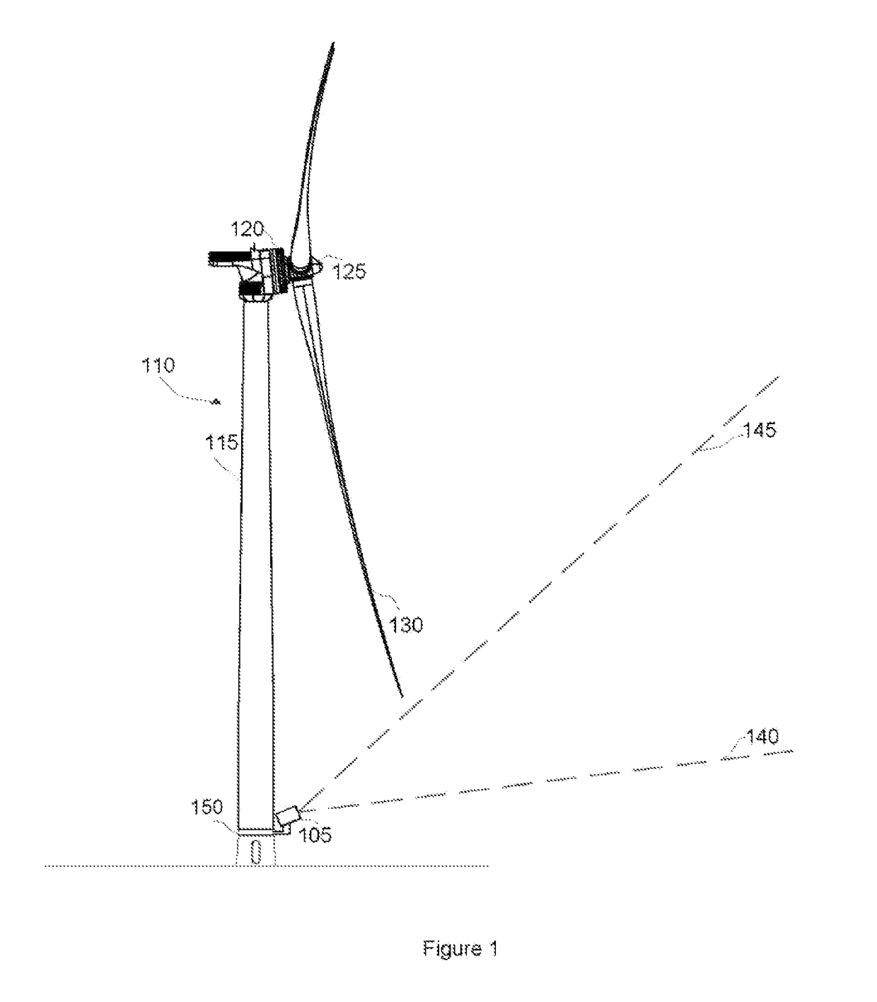
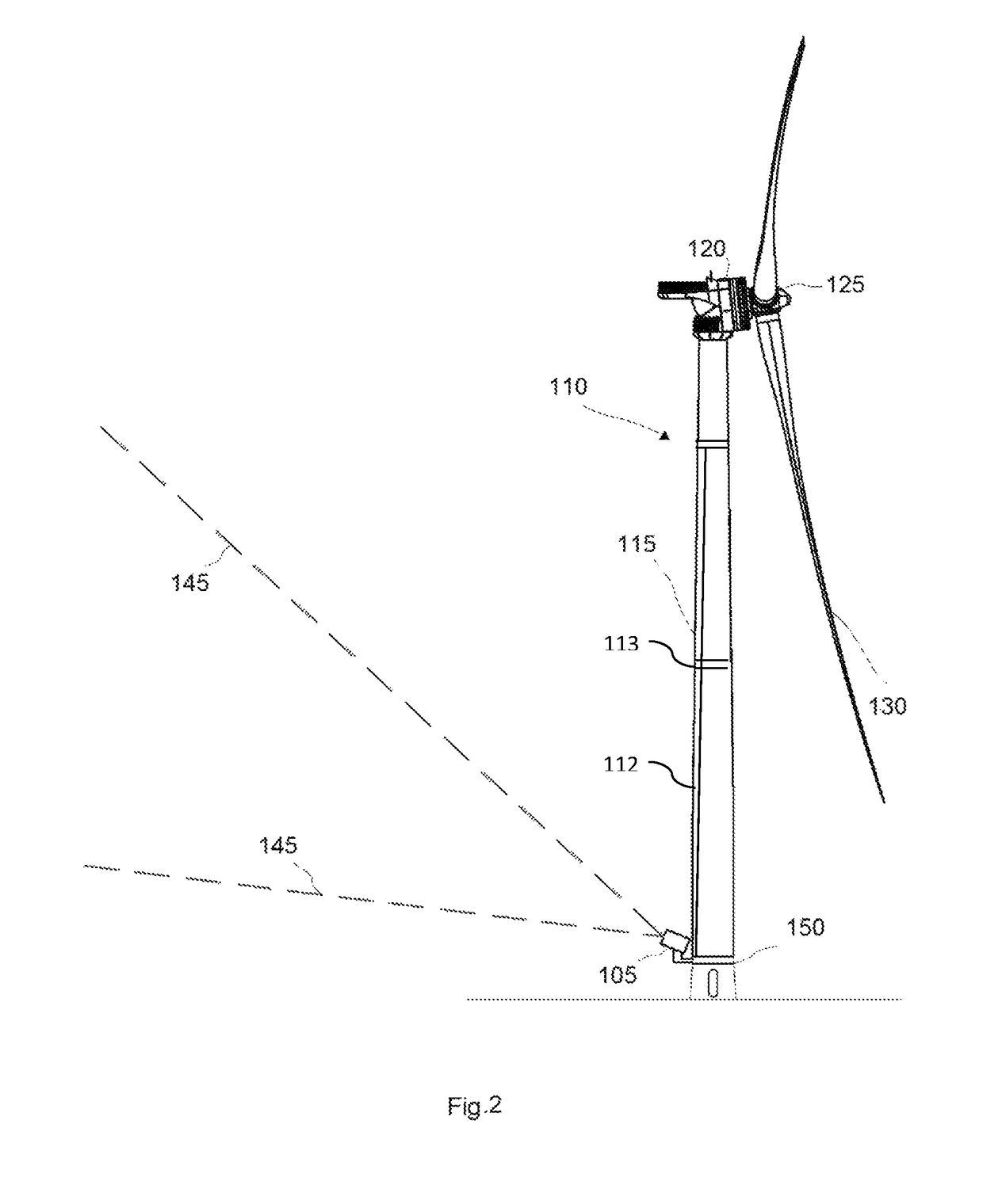
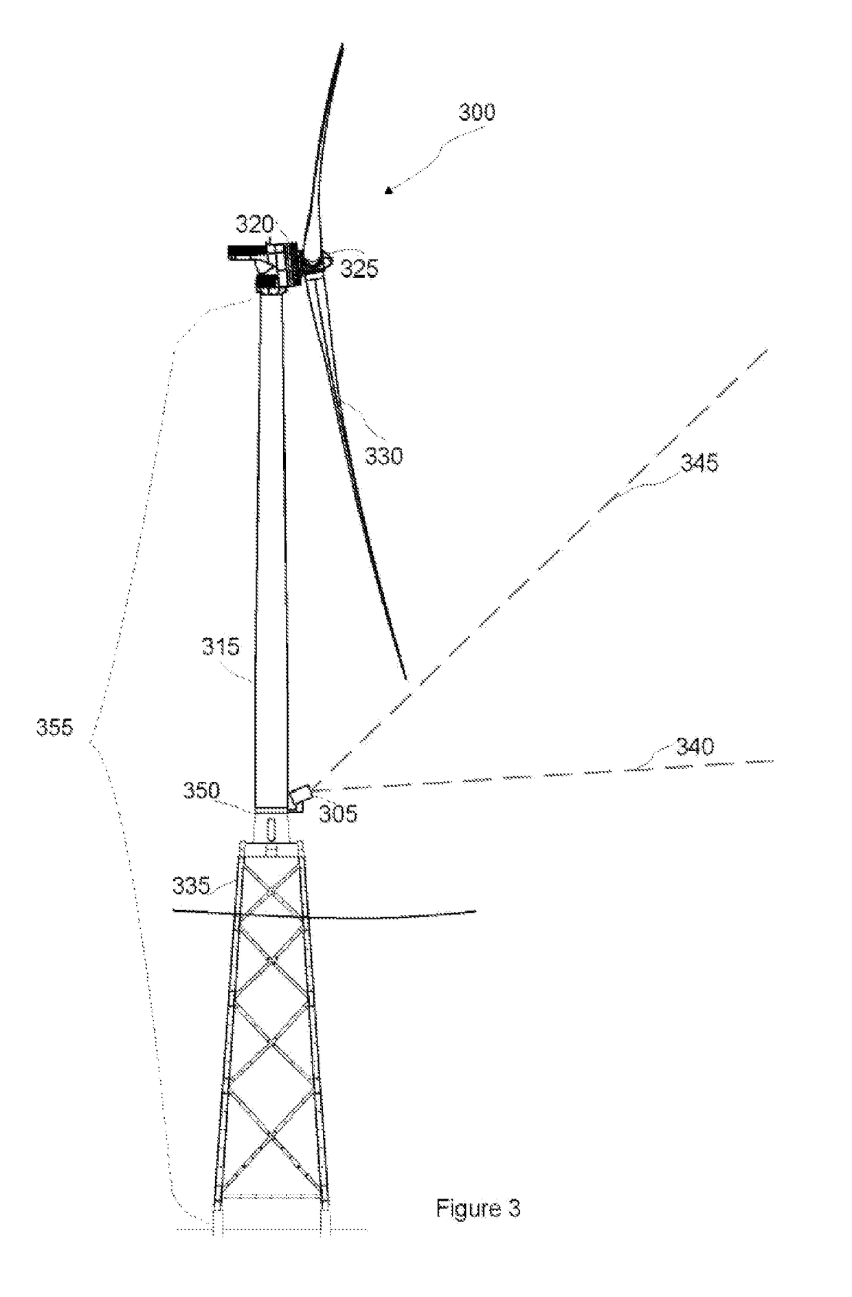
[0034]FIG. 1 illustrates an embodiment of a wind turbine according to the present invention. The wind turbine 110 comprises a tower 115, a nacelle 120, a rotor 125 and rotor blades 130. The LIDAR 105 is moveably mounted around the circumference of the tower on a guiding rail 150 at the base of the tower and is forward-facing for measuring incoming wind speed and fluctuations. The vertical scanning range of the LIDAR is illustrated with a lower limit 140 which may be substantially horizontal and an upper limit 145 which may be limited by the lowest travel path of the rotor blades.

[0035]The wind sensing apparatus for measuring wind fluctuations and wind speed in the atmosphere may use the Doppler Effect. Such remote wind sensing apparatuses may comprise LIDARs and / or SODARs. These wind sensing apparatuses may be moveably mounted to the tower base with the aid of a platform with horizontal and / or vertical mechanisms for moveably mounting it to the support structure e.g. guiding rails. ...


PUM


Abstract

A wind turbine including a rotor, a nacelle, a support structure for the nacelle and at least one wind sensing apparatus mounted on the support structure.

Description

[0001]This application claims the benefit of European Patent Application EP13382377.3 filed Sep. 30, 2013, the entire contents of which are hereby incorporated by reference in its entirety for all purposes.[0002]The present disclosure relates to wind turbines and wind anemometry.BACKGROUND ART[0003]The performance of wind turbines is affected by turbulent wind conditions that cause structural loads on the wind turbine and its components. Currently, structural loads may be reduced by measuring incoming wind speed and wind turbulence in front of the wind turbine with remote wind sensing apparatuses. The data gathered by the wind sensing apparatuses may be used by feed-forward wind turbine controllers to proactively compensate for wind velocity and direction changes prior to impingement of the air flow on the wind turbine e.g. by adjusting the yaw of the nacelle and pitch angle of the blades to protect components and maximize the performance of the wind turbine.[0004]A number of optica...

Claims


Application Information

Patent Timeline
Patent Type & Authority Patents(United States)
IPC IPC(8): F03D7/04F03D17/00
CPCF03D7/048F03D17/00Y02E10/723F05B2270/806F05B2270/8042F05B2270/322Y02E10/72
Inventor CANAL VILA, MARCARMET UNZETA, JORDI
Owner GE RENEWABLE TECH WIND BV
Learn More