
Vehicle lighting fixture

a technology for lighting fixtures and vehicles, applied in lighting and heating devices, instruments, semiconductor devices for light sources, etc., can solve the problems of uniform luminance reduction in the light exiting surface, and achieve the effect of uniform luminance of the entire light exiting surface and improved luxurious sens

Active Publication Date: 2019-01-08
STANLEY ELECTRIC CO LTD
View PDF7 Cites 2 Cited by
  • Summary
  • Abstract
  • Description
  • Claims
  • Application Information

AI Technical Summary

Benefits of technology

[0009]The presently disclosed subject matter as devised in view of these and other problems and features in association with the conventional art. According to an aspect of the presently disclosed subject matter, a vehicle lighting fixture can achieve uniform projection of light while being capable of providing improved luxurious sense of projected light.
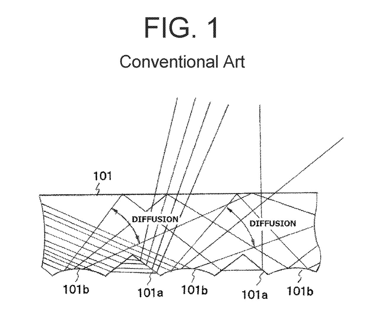
[0014]According to the vehicle lighting fixture of the first and second configurations, the light having entered the light guiding lens from the light source can be diffused by the plurality of flute cuts formed in the functional surface of the light guiding lens, so that the resulting light can be projected through the light exiting surface as smaller intensity light in a wider range. Thus, this configuration can achieve the uniform luminance of the entire light exiting surface.
[0015]Furthermore, the light having entered the light guiding lens from the light from the light source can be reflected by the plurality of prism cuts that are arranged at random on the functional surface of the light guiding lens, so that the light with larger intensity can be projected through the light exiting surface as larger intensity light (reflected light) in a narrower range. This configuration can provide the light exiting surface with jewel-toned brightness (glitter sense) due to dispersed bright spots, i.e., improved luxurious sense.
[0016]According to the vehicle lighting fixture of the third and fourth configurations, the plurality of flute cuts provided in the front and / or rear surfaces of the inner lens can diffuse light projected from the light guiding lens. Thus, dispersed bright spots can be evened slightly to suppress the glare of the projected light, so that modesty luxurious sense of projected light can be achieved.

Problems solved by technology

In a vehicle lighting fixture including such a light guiding lens, there is a large difference in luminance between a nearer position and a farther position from the light source, resulting in decreased uniform luminance in the light exiting surface.

Method used


Image

  • Vehicle lighting fixture
  • Vehicle lighting fixture
  • Vehicle lighting fixture

Examples


Embodiment Construction

[0027]A description will now be made below to a vehicle lighting fixture of the presently disclosed subject matter with reference to the accompanying drawings in accordance with exemplary embodiments.

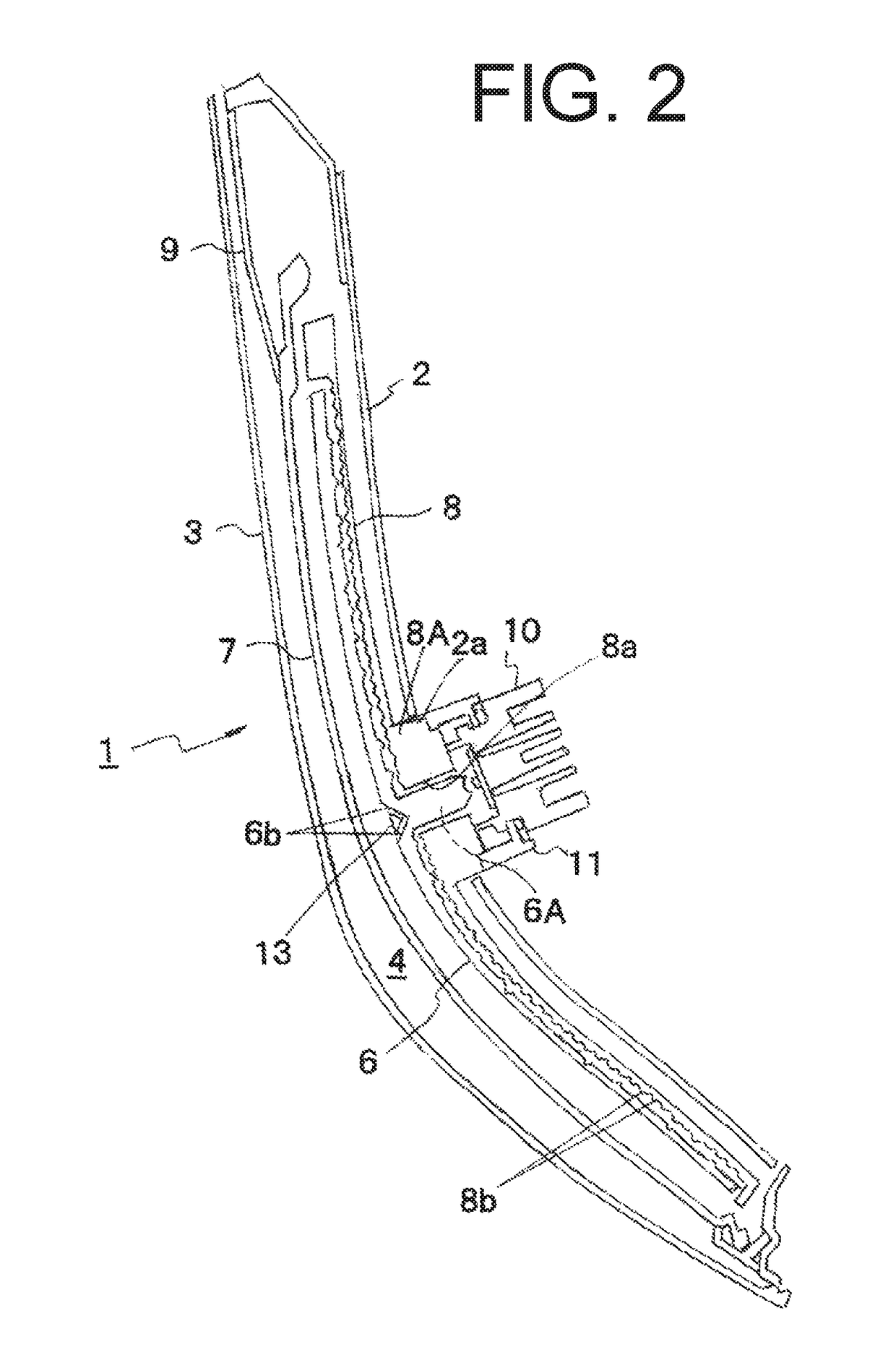
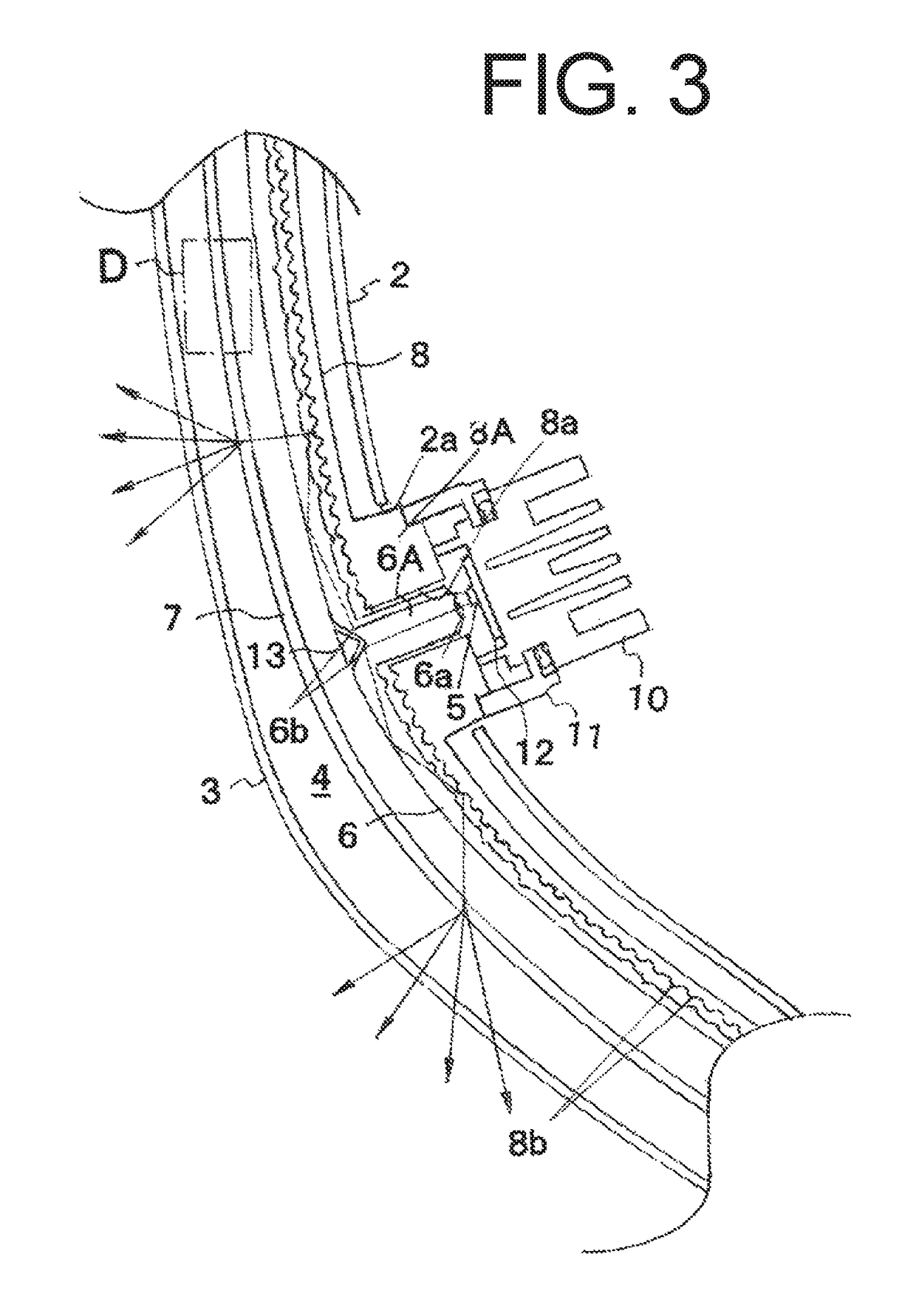
[0028]FIG. 2 is a horizontal cross-sectional view of a vehicle lighting fixture made in accordance with principles of the presently disclosed subject matter, and FIG. 3 is an enlarged horizontal cross-sectional view of essential portions of the vehicle lighting fixture in part illustrated in FIG. 2. FIG. 4 is a perspective view illustrating part of a light guiding lens of the vehicle lighting fixture, FIG. 5 is a cross-sectional view of the light guiding lens taken along line A-A of FIG. 4. FIG. 6 is a cross-sectional view of the light guiding lens taken along line B-B of FIG. 4, and FIG. 7 is a cross-sectional view of the light guiding lens taken along line C-C of FIG. 4. Furthermore, FIG. 8 is an enlarged cross-sectional view of an inner lens of the vehicle lighting fixture, in partic...


PUM


Abstract

A vehicle lighting fixture can achieve uniform projection of light while being capable of providing improved luxurious sense of projected light. The vehicle lighting fixture can include a housing, an outer lens configured to cover an opening of the housing to define a lighting chamber; and a light source and a light guiding lens located in the lighting chamber. The light guiding lens is configured so as to receive light from the light source and guide the light to a light exiting surface thereof for light projection. The light guiding lens has a functional surface which is opposite to the light exiting surface and can include a plurality of flute cuts configured to diffuse light and a plurality of prism cuts configured to reflect light. The plurality of prism cuts are arranged at random on the functional surface.

Description

[0001]This application claims the priority benefit under 35 U.S.C. § 119 of Japanese Patent Application No. 2016-032738 filed on Feb. 24, 2016, which is hereby incorporated in its entirety by reference.TECHNICAL FIELD[0002]The presently disclosed subject matter relates to a vehicle lighting fixture including a light source and a light guiding lens configured to guide light from the light source and allow it to exit therethrough.BACKGROUND ART[0003]Some conventionally known vehicle lighting fixtures used as a rear lamp or a position lamp include a light source such as a light emitting diode (LED) and a light guiding lens having a reflective function portion and a light exiting surface. In this type of lighting fixtures, light emitted from the light source can enter the light guiding lens and be guided by the reflective function portion thereof in its longitudinal direction. During the guiding of light, the light can be reflected, thereby exiting through the light exiting surface. In ...

Claims


Application Information

Patent Timeline
Patent Type & Authority Patents(United States)
IPC IPC(8): G02B6/34F21S43/245F21S43/247F21S43/31F21S45/48F21S43/239F21S43/20F21S43/235F21V8/00F21S45/47F21S43/14F21Y115/10
CPCF21S43/235F21S43/239F21S43/245F21S43/247F21S43/26F21S45/48G02B6/0031G02B6/0036F21S43/31F21Y2115/10F21S43/14F21S45/47
Inventor NAKASHIMA, DAISUKEIMAZEKI, NORIFUMI
Owner STANLEY ELECTRIC CO LTD
Learn More