
Location tracking using short-range infrared transmission

Active Publication Date: 2019-01-08
ADOBE INC
View PDF10 Cites 0 Cited by
  • Summary
  • Abstract
  • Description
  • Claims
  • Application Information

AI Technical Summary

Benefits of technology

The patent provides methods and systems for determining the location of a user in a venue using infrared technology. An IR receiver detects an IR signal from an IR transmitter on the user and sends the data to a location tracking system (LTS). The LTS then calculates the user's location based on the receiver's location and the limited transmission range of the IR transmitter. The technical effects of this technology include improved accuracy in determining user location and improved user experience in accessing the venue.

Problems solved by technology

While these techniques are sufficient for coarse location determination, they generally fail to provide sufficient information about a visitor to identify the particular areas of a venue a user visits or the items or people with which the user interacted.
For example, such techniques are generally not specific enough to identify that a user stopped to look at a particular item or portion of a shelf along an aisle of a store.
Similarly, conventional techniques are not sufficiently granular to distinguish when a user at a conference communicates with another user (as opposed to simply being relatively nearby without interacting with the other user).
Such techniques, however, require the user to carry a mobile device and generally rely upon the user cooperation and effort to load and use a particular application on the mobile device.
In addition, these techniques also generally lack sufficient granularity to accurately identify the particular areas of a venue visited or the people or items with which the user interacted.
Such techniques, however, are often expensive to deploy and generally, like the previously discussed techniques, also do not provide sufficient information to accurately identify the particular areas of a venue visited or the people or items with which the user interacted.

Method used


Image

  • Location tracking using short-range infrared transmission
  • Location tracking using short-range infrared transmission
  • Location tracking using short-range infrared transmission

Examples


example processes

[0062]The components of the example operating environment 100 are described hereinafter with reference to the example methods and diagrams illustrated in FIGS. 2-4. The example methods of FIGS. 2-4 may also be performed with other systems and in other environments.

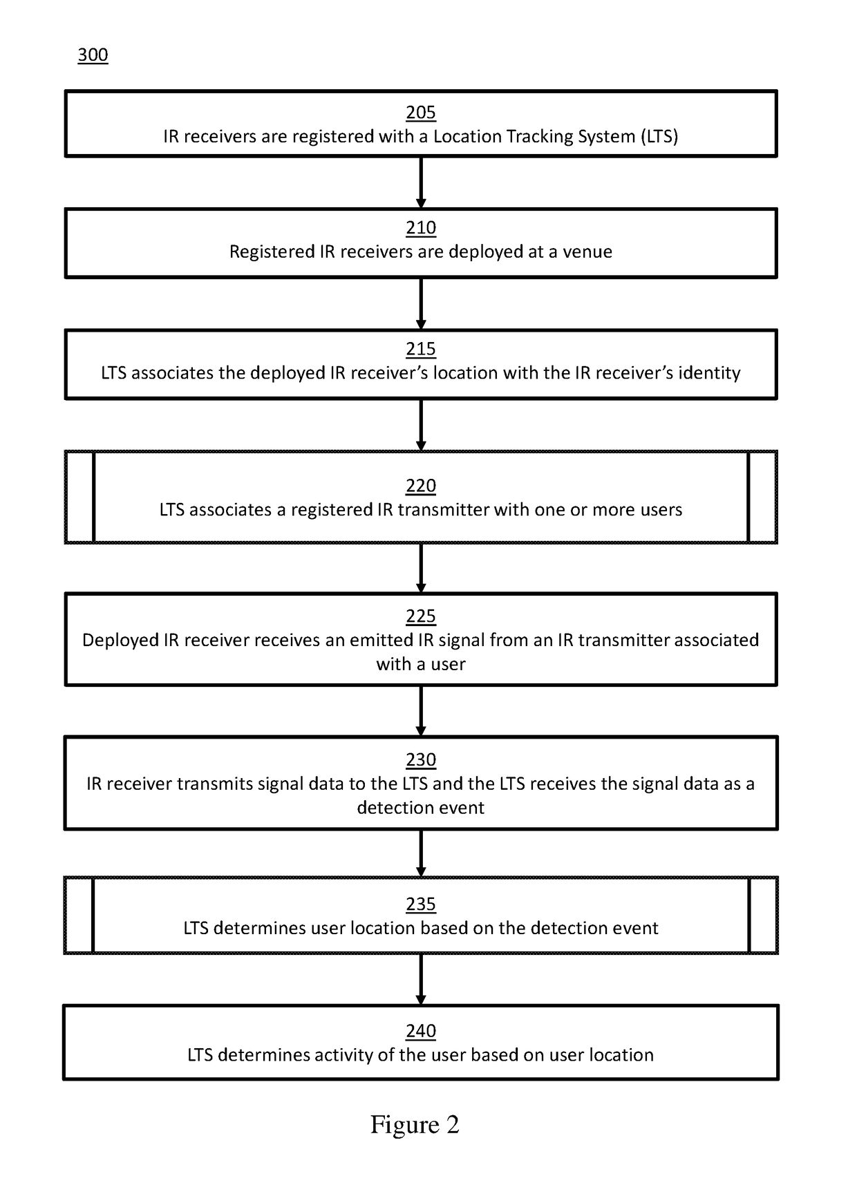
[0063]FIG. 2 is a block flow diagram depicting a method for determining a user location at a venue using infrared transmissions, in accordance with certain example embodiments.

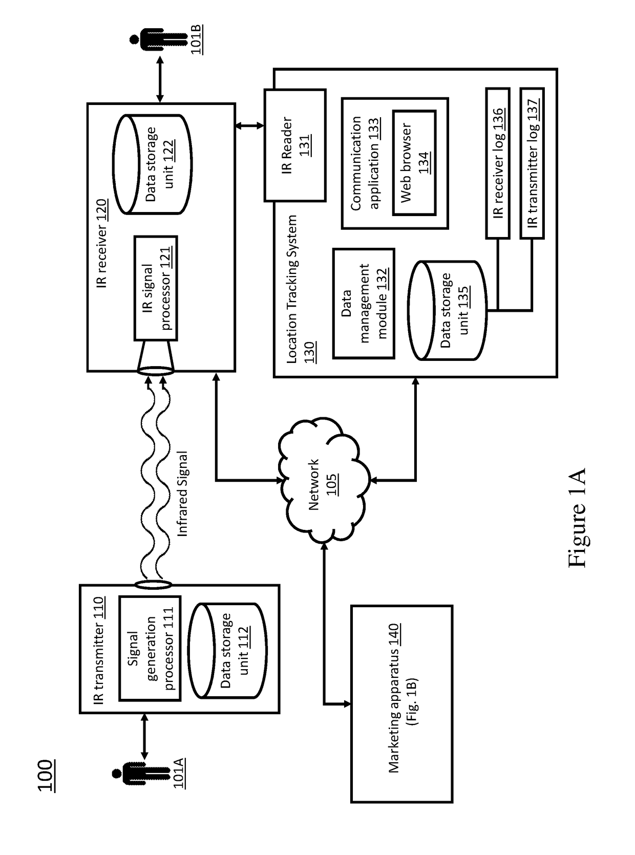
[0064]With reference to FIGS. 1A-1B and 2, in block 205 of FIG. 2, IR receivers 120 are registered with the LTS 130. That is, the identity of one or more IR receivers 120 is recorded in an IR receiver log 136 of the LTS 130. For example, an operator of the LTS 130 may scan the IR receivers 120 via the IR reader so that their identity is recorded with the LTS 130, such as in an IR receiver log 136 of the data storage unit 135 of the LTS 130. Additionally or alternatively, the operator may manually input the identity of each receiver into the LTS 130, ...


PUM


Abstract

Provided are methods and systems for improved user tracking via the exchange of information over narrow-beam infrared (IR) transmission. IR receivers are positioned around a venue. A limited-range, narrow-beam IR transmitter associated with a user sends IR signals that are received by the IR receiver when the IR transmitter is close enough to the receiver. The receiver then transmits signal data from the received signal to a back-end location tracking system (LTS) that aggregates and processes the received signal data as a detection event. Based on the detection event, the LTS determines the location of the IR receiver hence the location of the user. Because of the limited transmission range of the IR transmitter, analyzing the detection event allows precise determination of the user's location, orientation, and / or movements within the venue. The LTS can also determine the identity of the user.

Description

TECHNICAL FIELD[0001]The present disclosure relates generally to location determination, and more particularly to methods and systems for determining user location relative to another object or another user via the use of short-range infrared transmissions.BACKGROUND[0002]iBeacons and other radio frequency (RF)-based techniques are used to track visitors who visit stores and other venues. While these techniques are sufficient for coarse location determination, they generally fail to provide sufficient information about a visitor to identify the particular areas of a venue a user visits or the items or people with which the user interacted. For example, such techniques are generally not specific enough to identify that a user stopped to look at a particular item or portion of a shelf along an aisle of a store. Similarly, conventional techniques are not sufficiently granular to distinguish when a user at a conference communicates with another user (as opposed to simply being relativel...

Claims


Application Information

Patent Timeline
IPC IPC(8): H04B10/114H04B10/50H04B1/3827
CPCH04B10/114H04W4/33H04B10/50H04B1/385H04W4/029
Inventor BROWN, JAMESBELLOWS, JARED
Owner ADOBE INC
Features
  • Generate Ideas
  • Intellectual Property
  • Life Sciences
  • Materials
  • Tech Scout
  • Unparalleled Data Quality
  • Higher Quality Content
  • 60% Fewer Hallucinations
Learn More