
Cutting knife for a cutting head of a trimmer

a cutting knife and trimmer technology, applied in the direction of mowers, agriculture tools and machines, etc., can solve the problems of annoying and irritating noise, and achieve the effect of reducing the noise emission of rotating cutting knives and minimising nois

Active Publication Date: 2019-02-05
ANDREAS STIHL AG & CO KG
View PDF14 Cites 4 Cited by
  • Summary
  • Abstract
  • Description
  • Claims
  • Application Information

AI Technical Summary

Benefits of technology

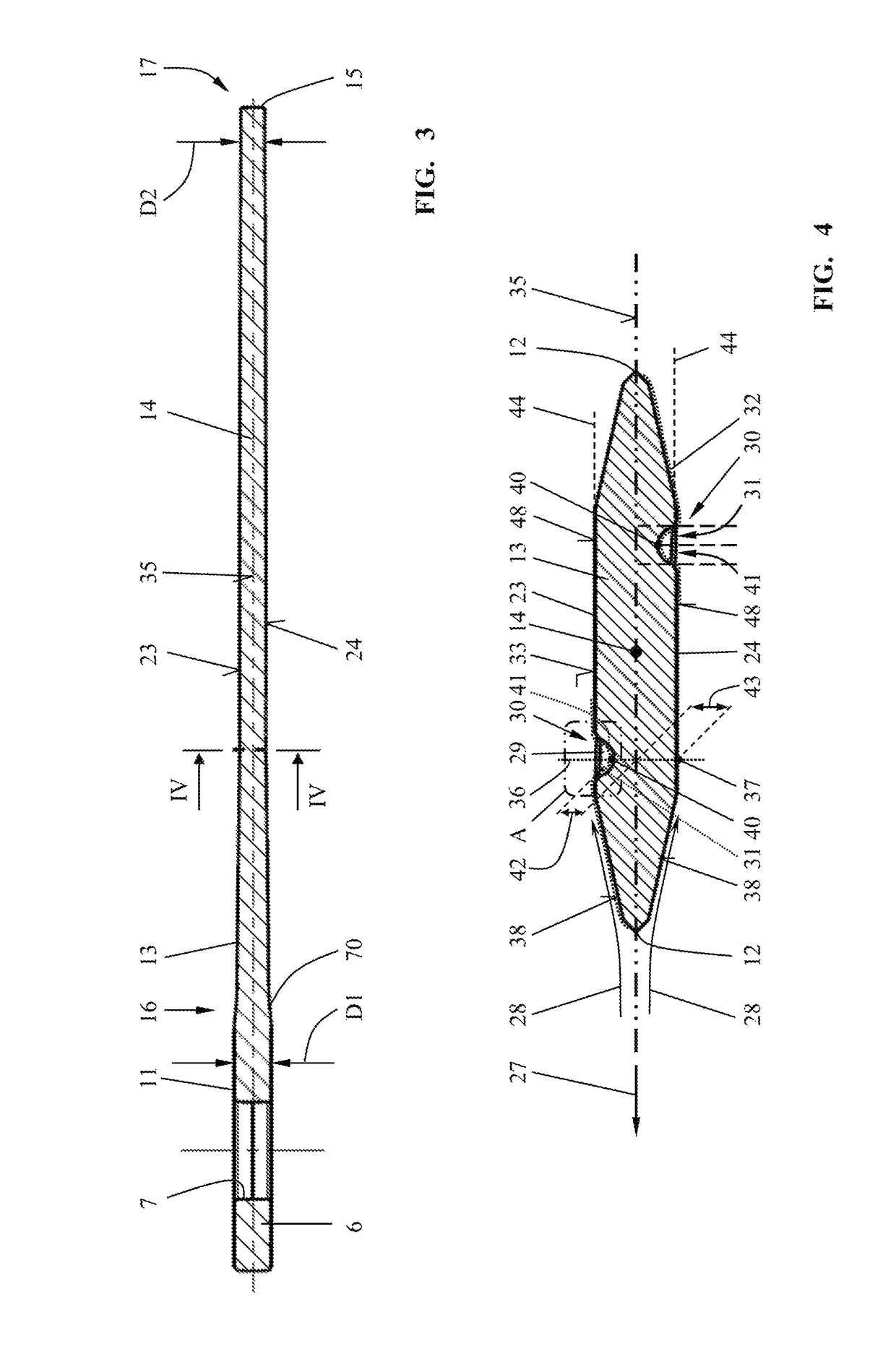
[0019]Due to this asymmetric configuration, it is achieved that the air flowing across the faces of the cutting knife is disturbed in its flow in the area of the topographic disturbance element so that, for example, on the upper face provided with a disturbance element, a different flow behavior results compared to the oppositely positioned lower face of the cutting knife which preferably does not comprise a disturbance element or comprises a disturbance element at a different location. The constructively provided disturbance element effects as a whole flow conditions on the cutting knife which significantly lower the noise emission of a rotating cutting knife. The cutting knife according to the invention for a cutting head of a trimmer exhibits only a minimal noise emission even at high rotational speeds.

Problems solved by technology

As a function of the rotary speed, the cutting knife that is circulating on a circular path generates a noise that is annoying and irritating, in particular in the load-free state of the cutting head.

Method used


Image

  • Cutting knife for a cutting head of a trimmer
  • Cutting knife for a cutting head of a trimmer
  • Cutting knife for a cutting head of a trimmer

Examples


Embodiment Construction

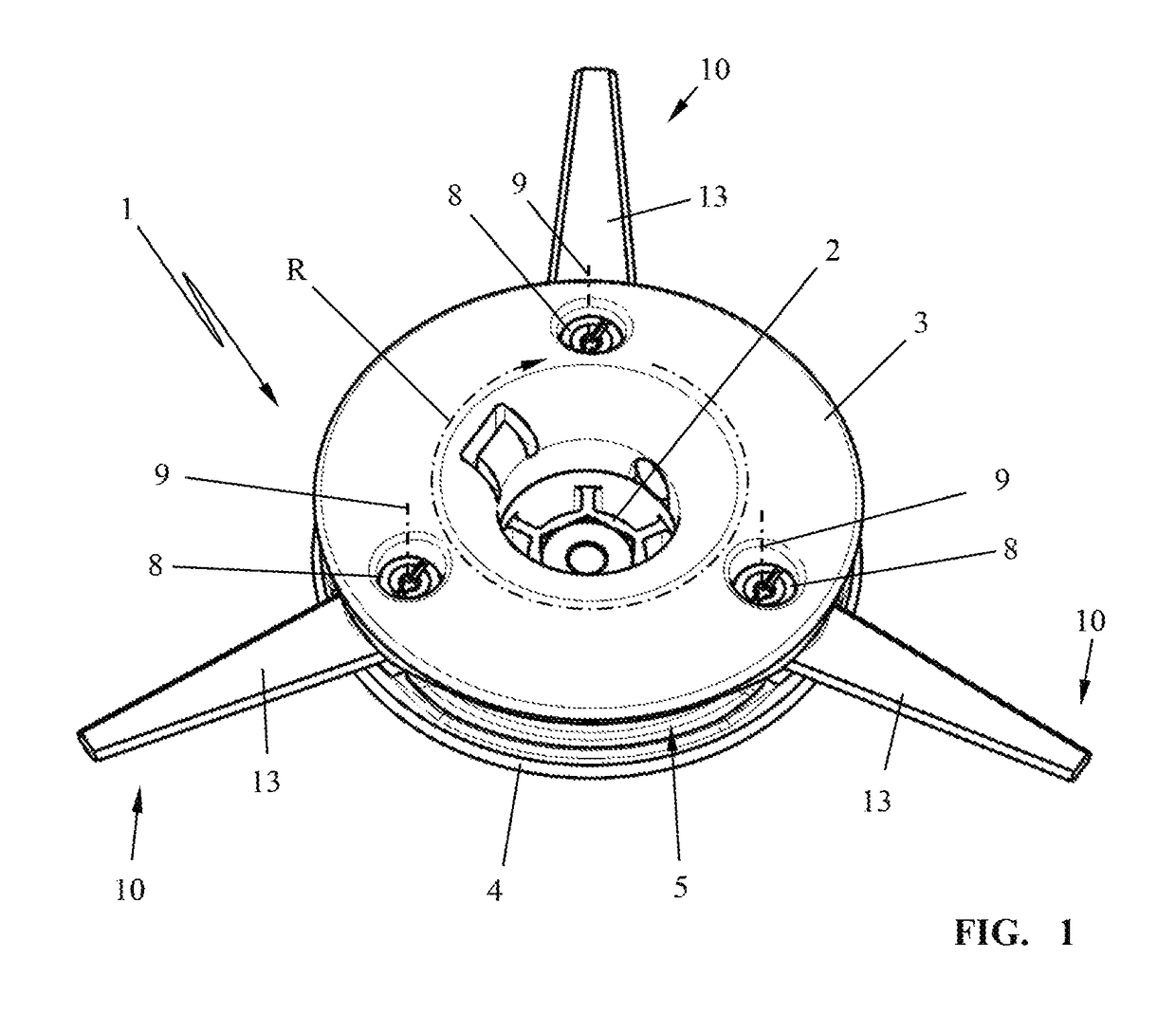
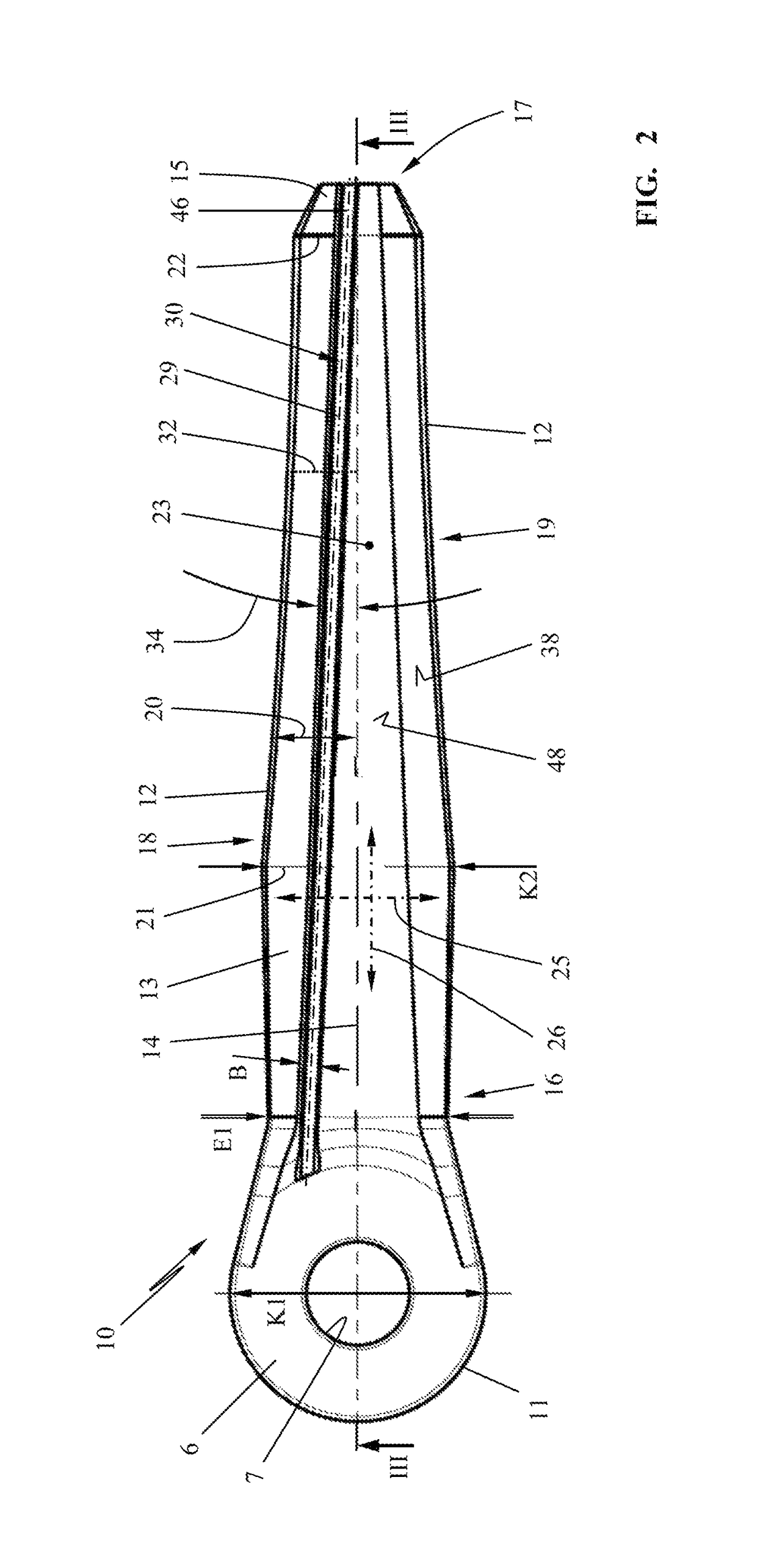
[0057]FIG. 1 illustrates a cutting head 1 which comprises a central receptacle 2 for mounting the cutting head 1 on a rotary drive shaft of a trimmer. The cutting head 1 is comprised of a top head part 3 and a bottom head part 4 which are connected fixedly to each other. Between the head parts 3 and 4 a circumferentially extending groove 5 can be formed in which a fastening end 6 (FIG. 2) of a cutting knife 10 is inserted. The fastening end 6 comprises in the illustrated embodiment a fastening section 11 with fastening contour comprising a through hole 7 for receiving a fastening bolt 8. The fastening bolt 8 penetrates the through hole 7 and is fixedly screwed with its threaded end into the bottom head part 4. In the embodiment, the cutting knife 10 is pivotable about the fastening bolt 8 about the pivot axis 9. Other mounting possibilities of the cutting knife 10 on the cutting head 1 can be expedient. The pivot axis 9 has a radial spacing relative to the center of the receptacle 2...


PUM


Abstract

The cutting knife has a base member with first and second faces. One face has a topographic disturbance element arranged between knife edge and longitudinal center axis and shaping the elevation profile of the face. On the opposite face relative to the center plane an opposite elevation profile with contour line is formed. The contour line points of the contour line of the first elevation profile are positioned opposite the contour line points of the opposite contour line on perpendiculars to the center plane. The contour line of the first elevation profile and the opposite contour line are noncongruent. The contour line of the first elevation profile extends transversely to the longitudinal center axis of the base member across the disturbance element and has an ascending line section and a descending line section. A turning point positioned between these line sections is a component of the disturbance element.

Description

BACKGROUND OF THE INVENTION[0001]The invention relates to a cutting knife for a cutting head of a trimmer. The cutting knife is comprised of a flat elongate base member that has a longitudinal center axis extending from a first end to a second end of the base member. The base member has longitudinal edges extending at a spacing to the longitudinal center axis from the first end to the second end of the base member. The base member has a first face and a second face between which a center plane is positioned, wherein the faces each are delimited in a first direction transverse to the longitudinal center axis by the longitudinal edges and, in a second direction along the longitudinal center axis, by the first end and the second end of the base member. On the first end of the base member, a fastening contour for mounting the cutting knife on the cutting head is provided. The second end of the base member comprises a free knife end of the cutting knife and a knife edge is formed on at l...

Claims


Application Information

Patent Timeline
Patent Type & Authority Patents(United States)
IPC IPC(8): A01D34/73A01D34/82
CPCA01D34/826A01D34/733A01D34/73
Inventor GUNTHER, DAVIDPOHLER, FABIAN
Owner ANDREAS STIHL AG & CO KG
Learn More