
Simplified construction of a photovoltaic system with a consecutively placed system block

a photovoltaic system and construction technology, applied in the field of photovoltaic systems, can solve the problems of insufficient assistance to the user of the software tool with the configuration of the photovoltaic system, and achieve the effects of reducing the time taken to generate a wide variety of potential (useful) photovoltaic systems, reducing the area of the system, and facilitating the determination of the structure of the pv system

Active Publication Date: 2019-02-12
SIEMENS AG
View PDF20 Cites 0 Cited by
  • Summary
  • Abstract
  • Description
  • Claims
  • Application Information

AI Technical Summary

Benefits of technology

This method reduces the time required to generate a wide variety of photovoltaic systems and facilitates the determination of the best compromise from various optimization objectives, enabling easier selection of the most suitable system configuration.

Problems solved by technology

However, existing software tools for the optimization of photovoltaic systems and the underlying concepts and methods follow a one-objective approach, as a result of which, by principle, they only assist the user of the software tool insufficiently with the configuration of the photovoltaic system.
Furthermore, such approaches tend to divide optimization scope into individual criteria.
One (technical) problem is that of simplifying and therefore accelerating the construction of photovoltaic systems as a multiplicity of possible systems, or increasing the number of available (useful) system possibilities in a simple manner so as to have (many) more options with a selection and definition of the correct or well-suited PV system.

Method used


Image

  • Simplified construction of a photovoltaic system with a consecutively placed system block
  • Simplified construction of a photovoltaic system with a consecutively placed system block
  • Simplified construction of a photovoltaic system with a consecutively placed system block

Examples


Embodiment Construction

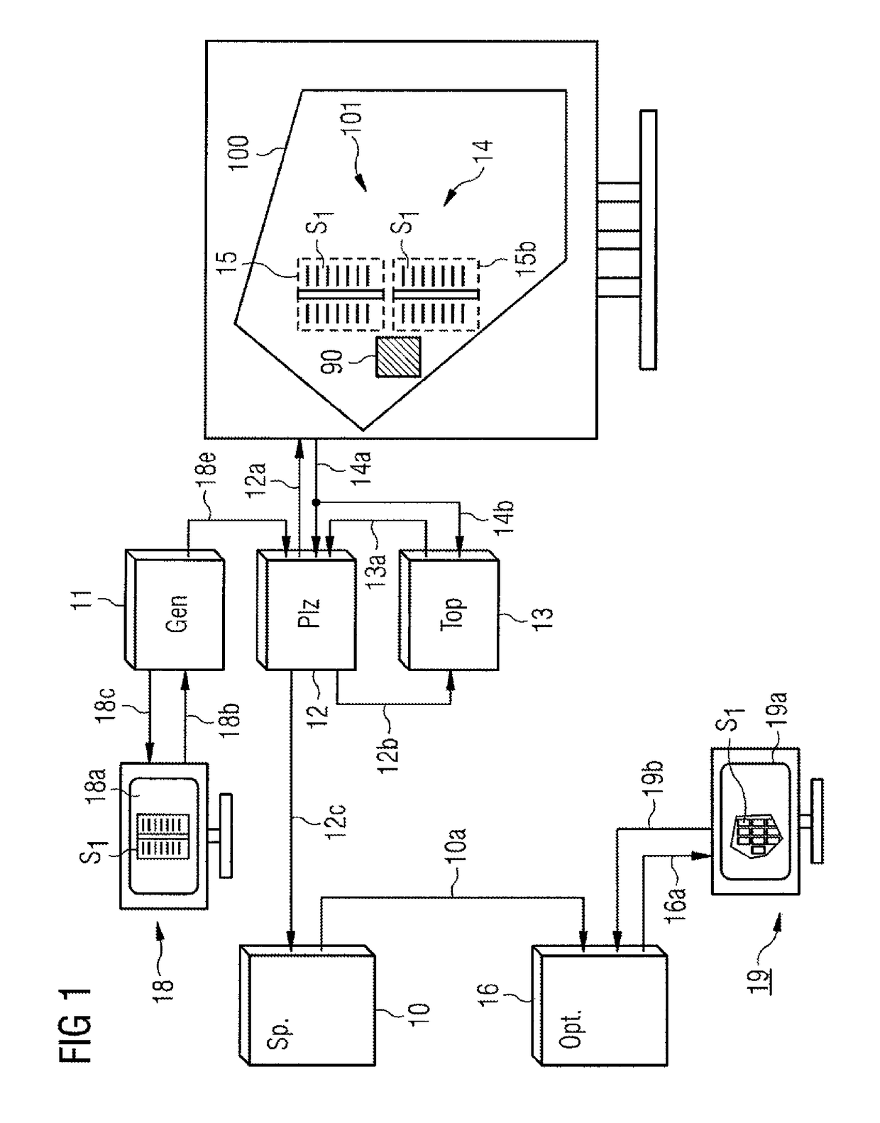
[0142]FIG. 1 shows a memory module 10, in which a multiplicity of layouts of photovoltaic systems are stored digitally. This memory can be formed for example as a database. The layouts, stored in the memory, of photovoltaic systems 101, 102, which will be explained later and which have been constructed in a “computer-assisted” manner in this example by at least one first computer 12, are read by a second computer 16 and are presented on an on-screen presentation 19a of a presentation arrangement 19.

[0143]The on-screen presentation 19a, which may be a printout or a presentation on a display, may have at least two highlighted regions, a coordinate region and an axis region, in which a multiplicity of parallel axes, illustrated as graphically represented sliders (axis with graphic slide buttons) are plotted.

[0144]FIG. 1 is a diagram with which the function is to be made understandable. To this end, individual functional components of the method as a whole are subdivided, assigned to de...


PUM


Abstract

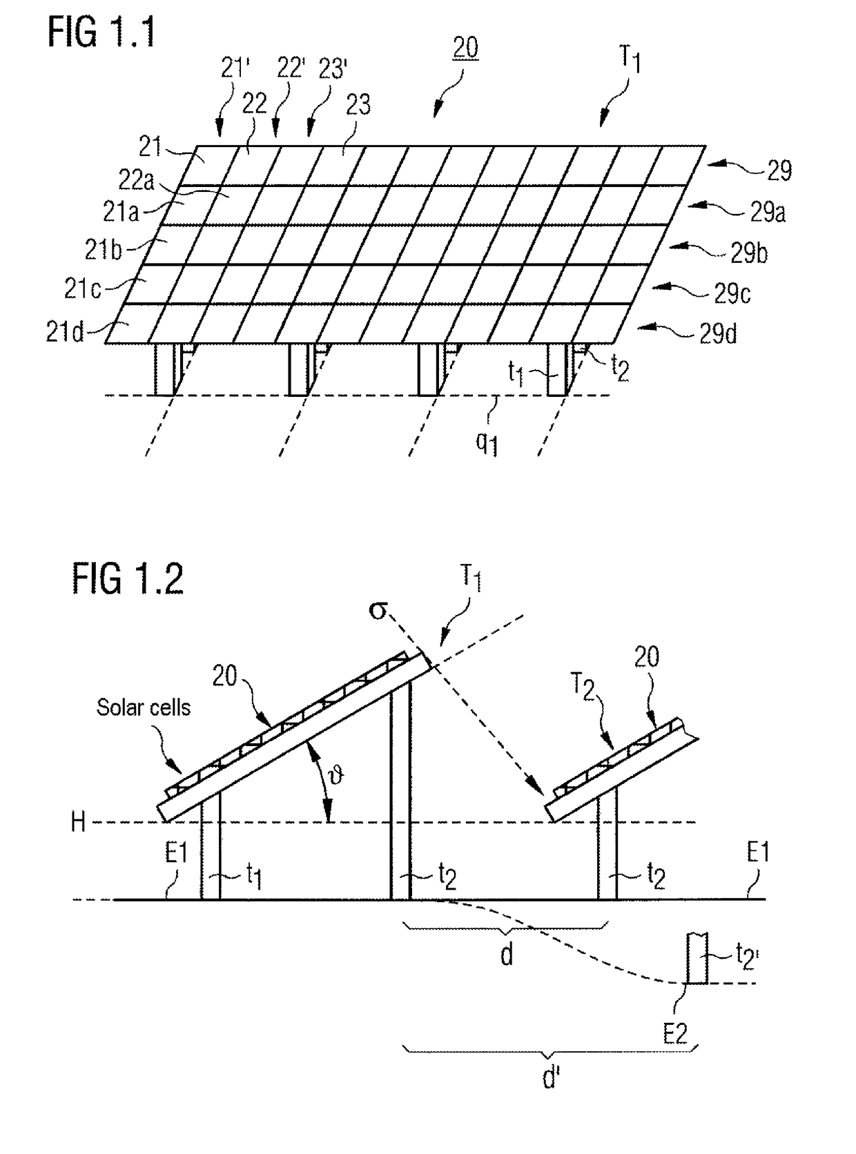
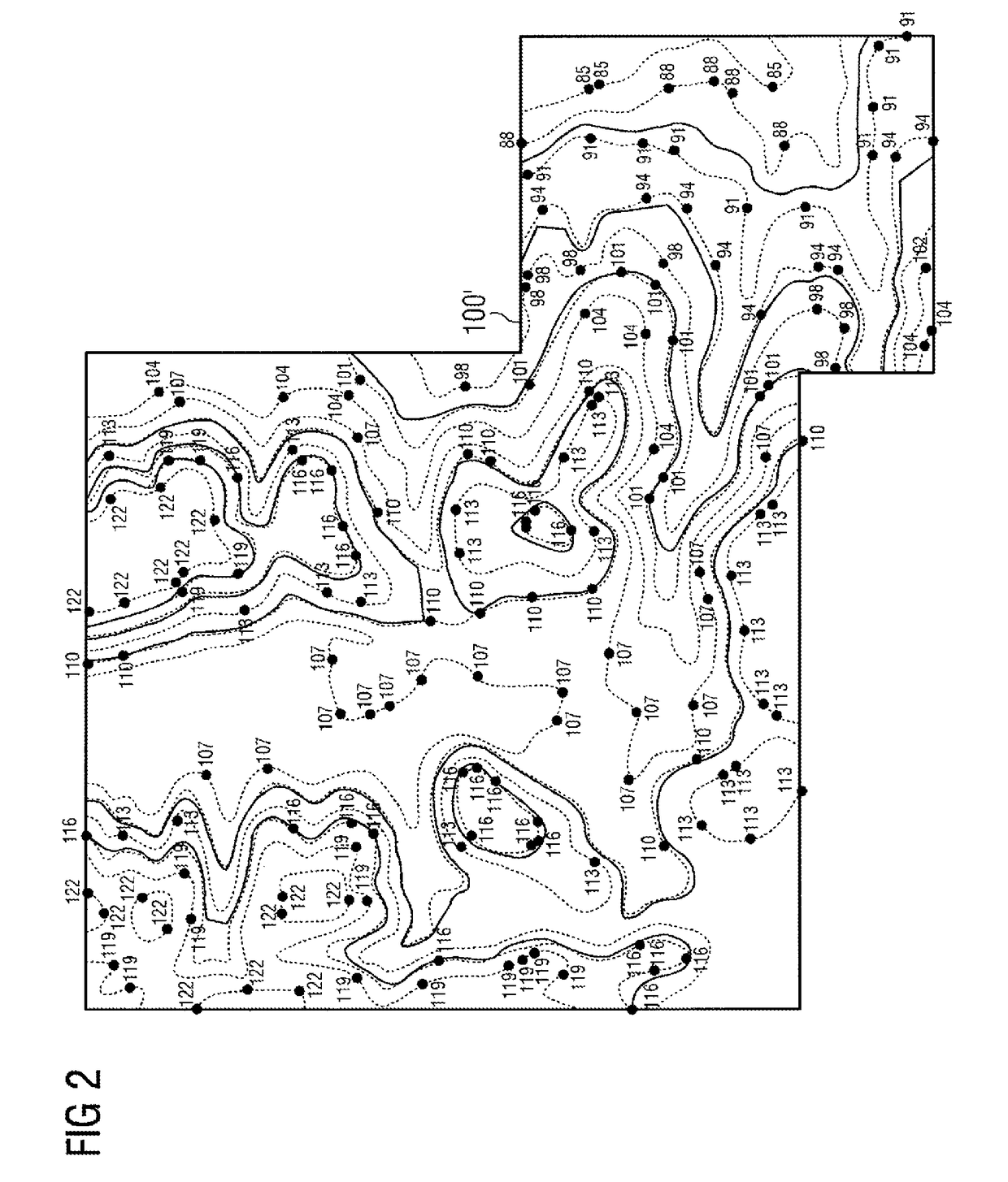
A method for defining a structure of a photovoltaic system on a system surface with a local topology is provided, including: first placement of a block at a location on the system surface with the local topology; placing additional blocks at additional locations on the system surface without overlapping previously placed blocks, wherein prior to each placement, row spacing of the solar panels of each additional block is adapted to the topology at the location at which the respective additional block was placed, resulting in a change in the extension of the additional block in the direction of the column of solar panels of the additional block, and ending the placement of additional blocks if, by the placement of an additional block, the nominal capacity of a photovoltaic system corresponding to the structure were to be exceeded, or if no additional block can be placed without overlapping previously placed blocks.

Description

CROSS REFERENCE TO RELATED APPLICATIONS[0001]This application is the US National Stage of International Application No. PCT / EP2012 / 071912 filed Nov. 6, 2012, and claims the benefit thereof. The International Application claims the benefit of German Application No. DE 10 2012 106 130.0 filed Jul. 7, 2012 and German Application No. DE 10 2012 100 197.9 filed Jan. 11, 2012. All of the applications are incorporated by reference herein in their entirety.FIELD OF INVENTION[0002]The present invention relates to photovoltaic systems (PV systems) in the sense of sun-operated power stations, layout thereof and construction thereof and therefore the provision of a number of optional structures that allow an “optimization” in view of properties of the PV power station and no longer offer only a one-shot configuration.BACKGROUND OF INVENTION[0003]There are a large number of partly contradictory optimization objectives when constructing and designing photovoltaic systems for power generation. In ...

Claims


Application Information

Patent Timeline
Patent Type & Authority Patents(United States)
IPC IPC(8): G06F17/50H02S20/00G06Q10/04
CPCG06F17/50H02S20/00G06Q10/043Y02E10/50G06F30/00
Inventor BISCHOFF, MARTINBRANDES, FREDERIKHENNIG, OLIVERKUFER, KARL-HEINZPLOCIENNIK, KAISCHULE, INGMAR
Owner SIEMENS AG
Learn More