Wearable pain monitor using accelerometry

a technology of accelerometry and pain monitor, which is applied in the field of wearable pain monitors, can solve the problems of different pain in unconscious patients, difficulty in concentrating, sweating, etc., and achieve the effect of not requiring a high degree of attention, convenient use for patients, and easy us

Active Publication Date: 2019-02-26
KONINKLJIJKE PHILIPS NV
View PDF16 Cites 13 Cited by
  • Summary
  • Abstract
  • Description
  • Claims
  • Application Information

AI Technical Summary

Benefits of technology

[0013]It is an object of the present invention to provide an unobtrusive device and method for monitoring pain of a user. Advantageously such an unobtrusive means of pain monitoring has a wide range of applications, before and during surgery and from post-operative recovery to chronic pain monitoring at home. Accordingly, operation of the device shall not demand particular skills to the user. Rather to the contrary, operation thereof needs to be self-explanatory. Another objective is the provision of an objective means of pain / stress scoring system which may be easily used by the patient and which does not require a high degree of attention. Still another objective resides in the provision of a device and method which may be easily used during normal daily activities. Still another objective is facilitating following up of pain development by a third person, such as a medical practitioner.

Problems solved by technology

Common signs of stress include sleeping problems, sweating, loss of appetite and difficulty of concentrating.
Pain in unconscious patients is different, since patient feedback cannot be retrieved.
It is clear that such subjective measures are difficult to evaluate and to generalize.
The required attention of the patient towards feeling pain may bias this estimation, making the assessment unreliable.
Although the above mentioned approaches take use of vital signs, none of them are actually unobtrusive as they are all based on a use of current modalities which are usually derived from an ECG with a functional heart, i.e. a heart producing output upon contraction.
Other problems of the known systems for measuring pain / stress reside in the usage of a large number of sensors which is burdensome to the patient, cumbersome as well as inconvenient during normal daily activity.

Method used


Image

  • Wearable pain monitor using accelerometry
  • Wearable pain monitor using accelerometry
  • Wearable pain monitor using accelerometry

Examples


Embodiment Construction

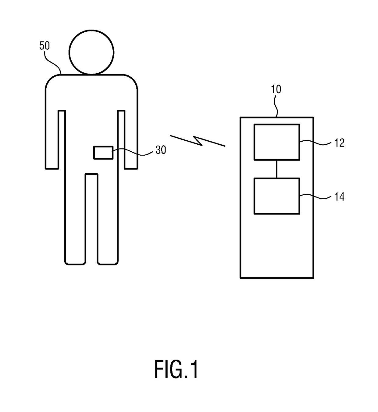
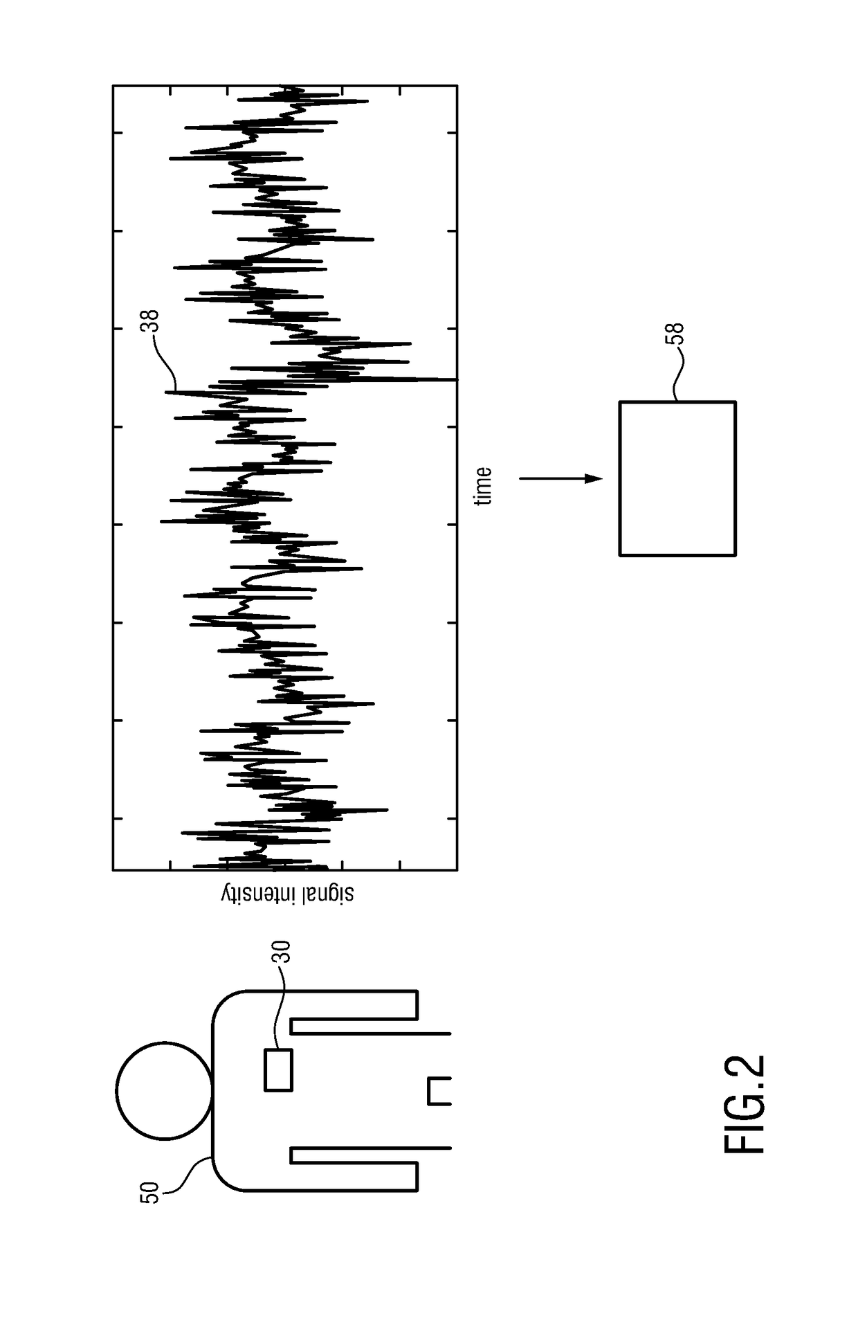
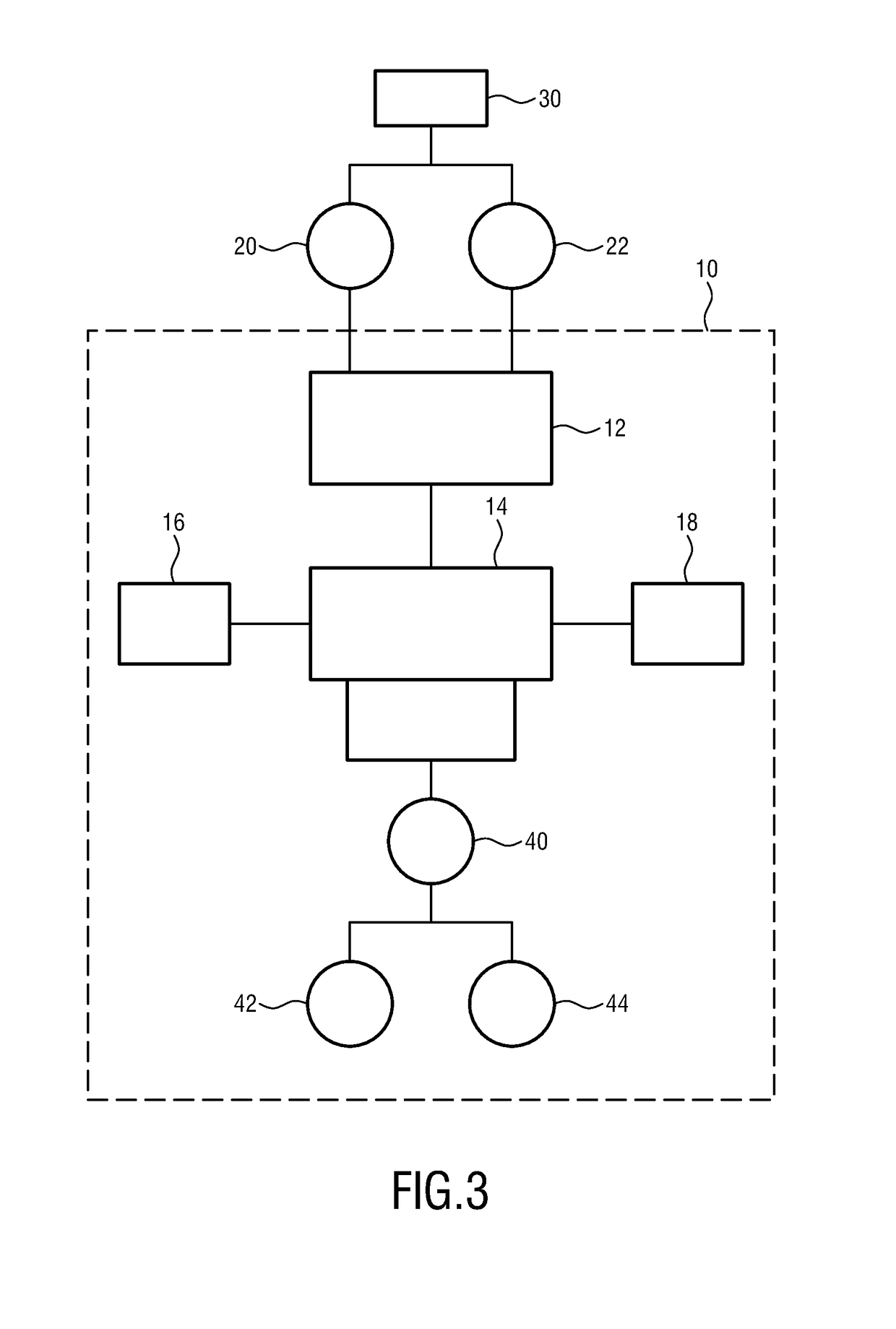
[0061]FIG. 1 schematically shows a user / subject 50 wearing an accelerometer 30 connected to the abdominal area. It will be appreciated that the accelerometer 30 may be worn at other parts of the human body including, for example, the chest, such as the sub-clavian part of the chest. Alternatively, the accelerometer 30 may be also implanted below the skin at any of these locations. The user 50 may also wear one or more accelerometers 30. In addition, the user may wear other sensors than an accelerometer. The accelerometer sensor 30 preferably wirelessly transmits an accelerometer signal to a remote device 10 for monitoring stress, discomfort and / or pain of a user 50. It will be appreciated that the invention is not limited to wireless transmission of signals from the sensor 30 to the device 10, but also includes wired transmission. This may hold true for all or a part of the sensors employed herein. The device 10 may be also realized in the same housing together with the sensor 30 an...


PUM


Abstract

A device and method for monitoring pain of a user (50) are presented. The device (10) comprises a receiving unit (12) for receiving an accelerometer signal (38) from an accelerometer sensor (30) worn by the user (50), wherein the accelerometer signal (38) comprises components of a pulse signal (20) and a respiration signal (22); and a processing unit (14) configured to: derive the pulse signal (20) and the respiration signal (22) from the accelerometer signal (38); adapt the pulse signal (20) based on the respiration signal (22) in order to obtain a corrected pulse signal (40); and derive a pain descriptor based on the corrected pulse signal (40).

Description

FIELD OF THE INVENTION[0001]The present invention relates to a monitoring apparatus and a corresponding monitoring method for monitoring pain of a user.BACKGROUND OF THE INVENTION[0002]Pain is a feeling triggered in the nervous system that can range from mild, localized discomfort to agony. Pain has both physical and emotional components. Its physical part results from nerve stimulation. Pain may be contained to a discrete area, as in an injury, or it can be more diffuse, as in disorders like fibromyalgia. It is mediated by specific nerve fibers that carry the pain impulses to the brain where their conscious appreciation may be modified by many factors. Stress is the feeling of being under too much mental or emotional pressure. Common signs of stress include sleeping problems, sweating, loss of appetite and difficulty of concentrating. The identification of pain and stress periods may be helpful in diagnosing health issues. Pain in unconscious patients is different, since patient fe...

Claims


Application Information

Patent Timeline
Patent Type & Authority Patents(United States)
IPC IPC(8): A61B5/04A61B5/113A61B5/02A61B5/00A61B5/08A61B5/024A61B5/0205A61B5/11
CPCA61B5/4824A61B5/02438A61B5/113A61B5/6823A61B5/7239A61B5/0002A61B2562/0219A61B5/02405A61B5/0816A61B5/1112A61B5/1118A61B5/7278A61B5/0205G16H40/63G16H50/20
Inventor ATALLAH, LOUIS NICOLASDELLIMORE, KIRAN HAMILTON J.DIRKES, MARCEL CORNELISMUHLSTEFF, JENS
Owner KONINKLJIJKE PHILIPS NV
Why Eureka
Try Eureka