Heat exchanger and production method for heat exchanger

a technology of heat exchanger and production method, which is applied in the direction of indirect heat exchangers, lighting and heating apparatus, laminated elements, etc., can solve the problems of increasing the complicated internal structure and achieves the effect of simplifying the internal structure of the stacked heat exchanger and reducing the production cost of the heat exchanger

Active Publication Date: 2019-02-26
KOBE STEEL LTD
View PDF20 Cites 7 Cited by
  • Summary
  • Abstract
  • Description
  • Claims
  • Application Information

AI Technical Summary

Benefits of technology

[0006]An object of the present invention is to simplify the internal structure of the stacked heat exchanger and to reduce the production cost of the heat exchanger.

Problems solved by technology

However, in the conventional heat exchanger, a plurality of through holes having different shapes are formed in the respective plates, and those through holes are formed in a state that different arrangement patterns are intermingled, therefore there is a problem that the internal structure of the heat exchanger is complicated and the production cost of the heat exchanger increases.

Method used


Image

  • Heat exchanger and production method for heat exchanger
  • Heat exchanger and production method for heat exchanger
  • Heat exchanger and production method for heat exchanger

Examples


Embodiment Construction

[0021]Hereinafter, embodiments of the present invention will be described with reference to the drawings.

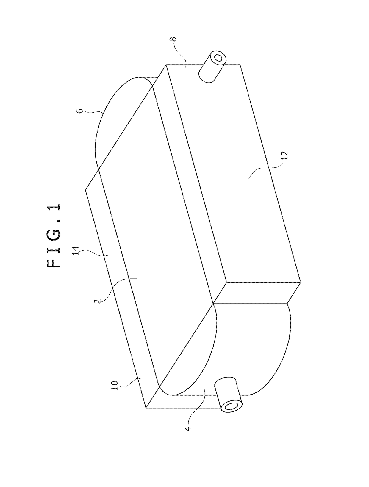
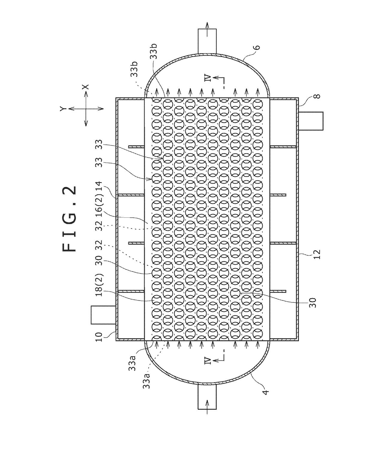
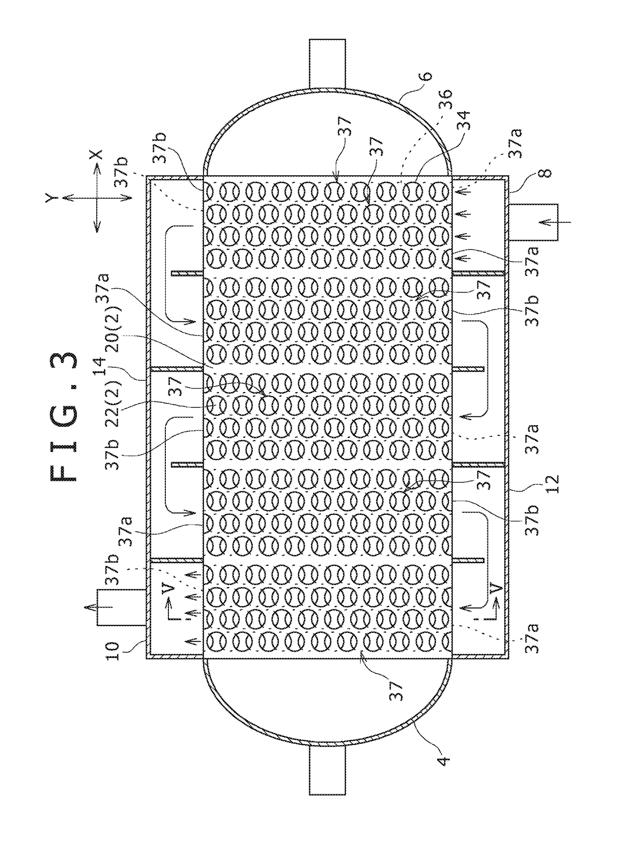
[0022]A heat exchanger according to an embodiment of the present invention allows a first fluid and a second fluid to exchange heat therebetween while allowing those fluids to circulate. For example, the heat exchanger of the present embodiment is used for cooling of hot oil with a cooling water, cooling of the gas compressed by a compressor with a cooling water, and the like. As shown in FIG. 1, the heat exchanger of the present embodiment is provided with a stacking block 2, a first supply header 4, a first discharge header 6, a second supply header 8, a second discharge header 10, a one side circulation header 12, and an other side circulation header 14.

[0023]The stacking block 2 is formed by a plurality of first flow path plates 16 (see FIG. 4), a plurality of second flow path plates 18, a plurality of third flow path plates 20, a plurality of fourth flow path plates 22, a pl...


PUM


Abstract

A heat exchanger including a stacking block, including: a first plate surface; a second plate surface opposite to the first plate surface; and first and second flow path plates including respective plural first and second through holes that have a standard shape. The first through holes are arranged to line up in a standard array pattern in a first direction in which a first flow path causes a first fluid to flow. The second through holes are arranged in the first direction in the same standard array pattern as the first through holes. Each of the first through holes have an area with a same overlap with the second through holes positioned on both sides of the first through holes, in the first direction. The first flow path is formed by the first and second through holes being mutually joined in the first direction, in the areas of overlap.

Description

TECHNICAL FIELD[0001]The present invention relates to a heat exchanger and a production method of the heat exchanger.BACKGROUND ART[0002]Conventionally, a stacked heat exchanger whose flow paths are formed by stacking a plurality of plates formed with a plurality of through holes respectively and communicating the through holes of the respective plates is known. In the following Patent Document 1, one such example of the stacked heat exchanger is shown.[0003]In the heat exchanger disclosed in the following Patent Document 1, the respective stacked plates constituting the heat exchanger are formed with a lot of through holes respectively. The lot of through holes formed in the respective plates include elongated holes extending linearly, elongated holes bent at a right angle, and elongated holes bent in a dogleg shape, or the like. The lot of through holes formed in the respective plates are arranged so as to line up along a predetermined direction respectively, and the arrangement d...

Claims


Application Information

Patent Timeline
Patent Type & Authority Patents(United States)
IPC IPC(8): F28D9/00F28F3/08F28F9/02F28F13/06F28F13/12
CPCF28D9/0068F28D9/0037F28D9/0062F28D9/0075F28F13/12F28F3/086F28F9/0204F28F9/0214F28F13/06F28F3/08
Inventor NOISHIKI, KOJIKUBO, YOHEIYAMADA, SAYAKA
Owner KOBE STEEL LTD
Why Eureka
Try Eureka