
Airbag for vehicle

Inactive Publication Date: 2013-06-13
HYUNDAI MOTOR CO LTD
View PDF1 Cites 27 Cited by
  • Summary
  • Abstract
  • Description
  • Claims
  • Application Information

AI Technical Summary

Benefits of technology

The present invention is about an improved airbag design for vehicles that reduces the risk of injury during deployment and increases the space within the airbag cushion. This is achieved by controlling the rate at which gas is released from the cushion through vents and by using a tube that contracts to reduce the pressure in the cushion during initial deployment and to quickly discharge gas when an occupant applies weight to the cushion. The reduced number of vents also simplifies the airbag cushion's production process and allows for easy design without restricting the shape of the cushion.

Problems solved by technology

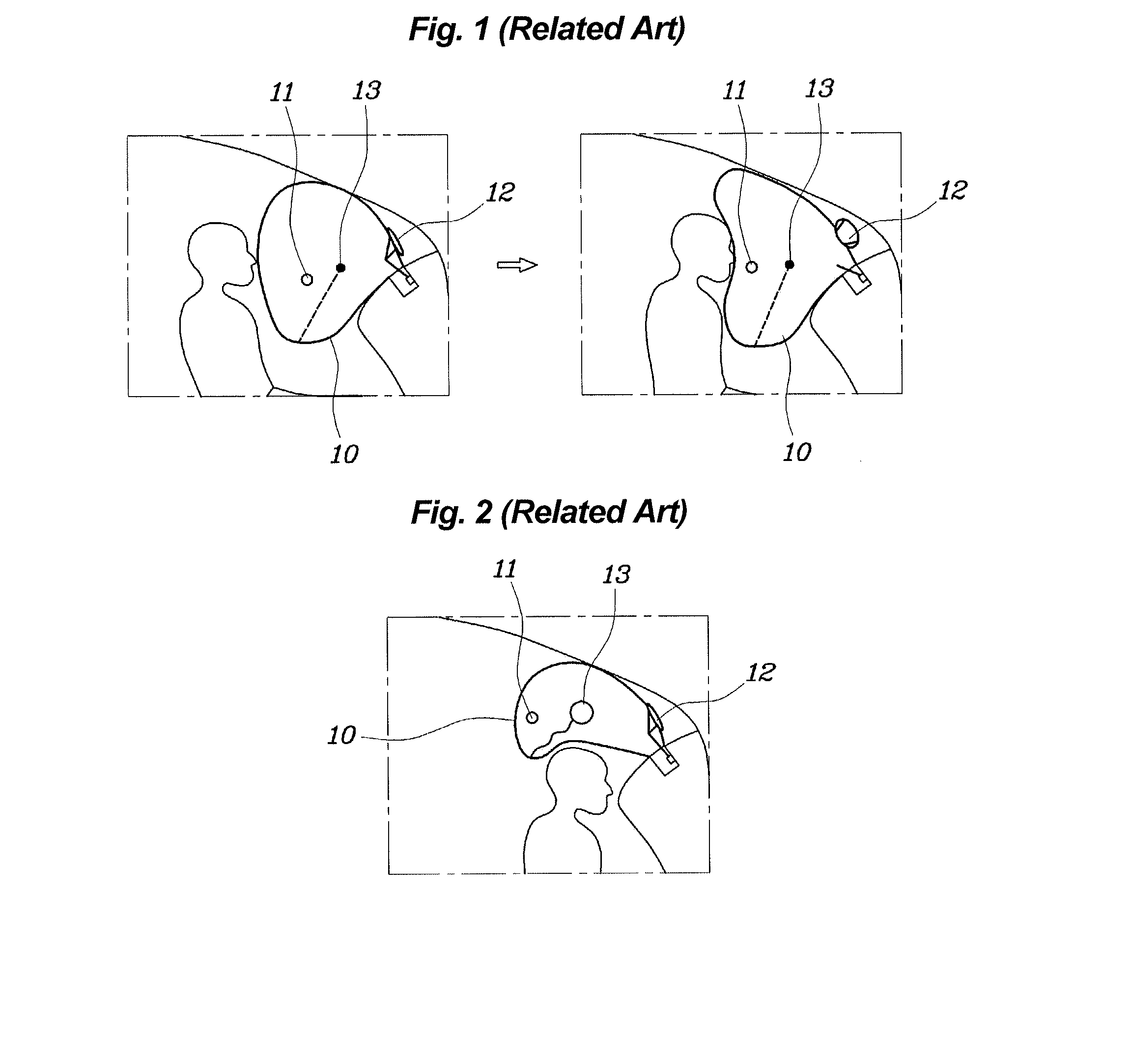
However, if the pressure in the airbag cushion when deploying is comparatively high in order to reliably reduce the risk of injuring the neck of the occupant, the back of the head of the occupant may be made to strike the headrest of a seat by the instantaneous inflation pressure of the airbag cushion, resulting in the occupant injuring his / her head.
However, in this conventional airbag cushion, because the vents open even at the initial stage of deployment of the airbag cushion, an excessive pressure loss may be caused during the deployment of the airbag cushion.
Thereby, the airbag cushion may not be able to correctly restrain the occupant at the initial stage of the vehicle collision, thus inducing a change in the conditions related to the injury of the occupant.
However, in this conventional technique, the number of vents through which gas is discharged from the airbag cushion is increased, thus excessively increasing a rate at which gas is discharged from the airbag cushion.
Therefore, the pressure in the airbag cushion decreases excessively rapidly, and the volume with which the airbag cushion deploys is reduced, thus increasing the risk of injuring the occupant.
In addition, the structure having the increased number of vents in the airbag cushion makes the internal shape of the airbag cushion complex, resulting in increasing the production cost of the airbag cushion, and reducing the degree of freedom in the shape of the airbag cushion, thereby making the design of the airbag cushion difficult.

Method used


Image

  • Airbag for vehicle
  • Airbag for vehicle
  • Airbag for vehicle

Examples


Embodiment Construction

[0039]Reference will now be made in detail to various embodiments of the present invention(s), examples of which are illustrated in the accompanying drawings and described below. While the invention(s) will be described in conjunction with exemplary embodiments, it will be understood that the present description is not intended to limit the invention(s) to those exemplary embodiments. On the contrary, the invention(s) is / are intended to cover not only the exemplary embodiments, but also various alternatives, modifications, equivalents and other embodiments, which may be included within the spirit and scope of the invention as defined by the appended claims.

[0040]Hereinafter, an embodiment of the present invention will be described in detail with reference to the attached drawings.

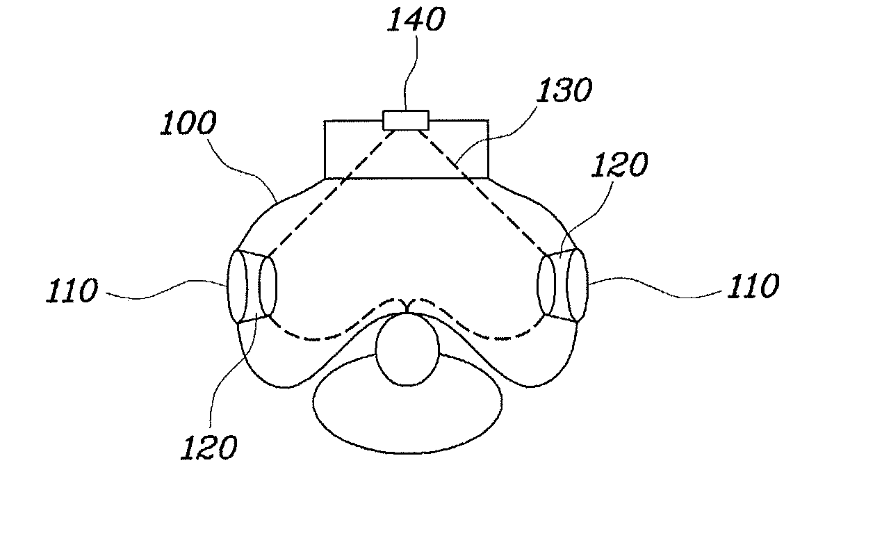
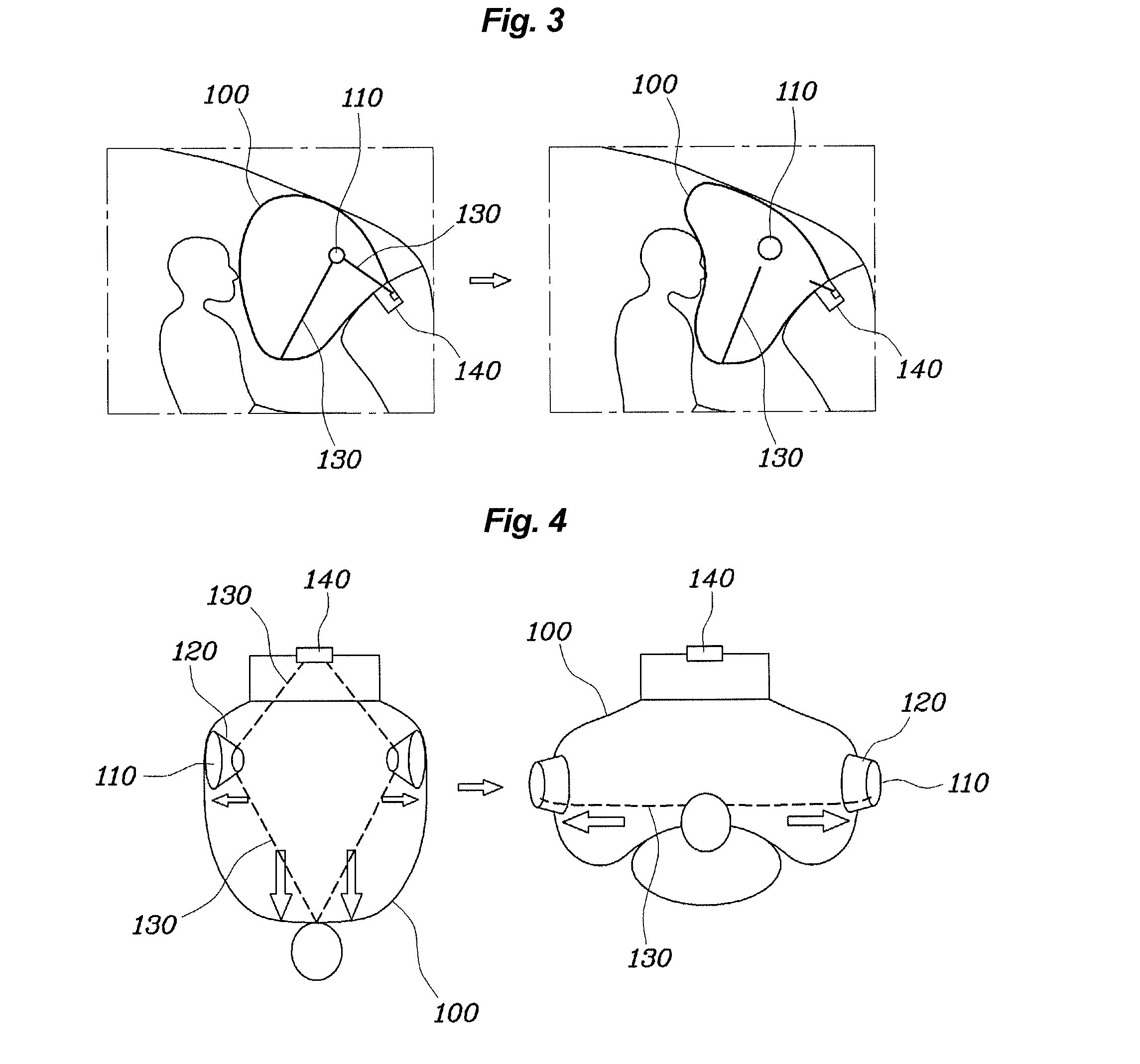
[0041]As shown in FIGS. 3 through 7, an airbag for a vehicle according to an exemplary embodiment of the present invention includes an integrated vent 110, a tube 120 and a tether 130. The integrated vent 1...


PUM


Abstract

An airbag apparatus for a vehicle, may include an integrated vent formed in an airbag cushion, a tube provided on the airbag cushion and communicating with the integrated vent, wherein an inner diameter of the tube varies while gas may be discharged through the tube, so that a rate at which gas may be discharged from the airbag cushion may be adjusted according to a point of time of deployment of the airbag cushion, and a tether wrapped around the tube, the tether being connected to inner surface of the airbag cushion such that opposite ends of the tether may be pulled away from each other when the airbag cushion deploys, so that in a predetermined time period of the deployment of the airbag cushion, the tether contracts the tube, and after the predetermined time period, the tether snaps, thus releasing the tube.

Description

CROSS-REFERENCE TO RELATED APPLICATIONS[0001]The present application claims priority to Korean Patent Application No. 10-2011-0131862 filed on Dec. 9, 2011, the entire contents of which is incorporated herein for purposes by this reference.BACKGROUND OF THE INVENTION[0002]1. Field of the Invention[0003]The present invention relates to an airbag for a vehicle which is configured such that the number of vents formed in an airbag cushion is reduced and a rate at which gas is discharged from the airbag cushion is appropriately controlled, thus reducing the risk of injuring an occupant, and increasing the degree of freedom in design of the airbag cushion.[0004]2. Description of Related Art[0005]Generally, airbag systems are installed in a vehicle to protect occupants in the vehicle from impact during a vehicle collision.[0006]In the airbag system, an airbag cushion is normally installed in an airbag housing in a folded state. In case of a vehicle collision, an inflator rapidly supplies g...

Claims


Application Information

Patent Timeline
IPC IPC(8): B60R21/2338
CPCB60R21/2338B60R2021/2395B60R2021/23384B60R21/239B60R21/20B60R21/2334
Inventor SHIN, HYO SHUBHO CHOI, HYEONGKIM, TAE INJANG, JUNG YEOLYOO, JAE HAENG
Owner HYUNDAI MOTOR CO LTD
Learn More