Obstetric device

a technology for obstetric devices and fetuses, applied in the field of obstetric devices, can solve the problems of affecting or settling the fetus in the birth canal, requiring considerable force, and limited space, and achieve the effect of efficient and safe delivery of the fetus

Active Publication Date: 2019-03-05
GUYS & ST THOMAS NHS FOUND TRUST
View PDF18 Cites 0 Cited by
  • Summary
  • Abstract
  • Description
  • Claims
  • Application Information

AI Technical Summary

Benefits of technology

[0008]In accord with the present invention, an obstetrical device which provides for a more efficient and safe delivery of a fetus has now been devised.
[0011]It is preferred that the peripheral rim has a peripheral wall extending to the floor of the cavity and the support lug or lugs are spaced from the peripheral wall. This enhances the general ability of the peripheral wall / rim to deform with respect to and independently of the support lugs
[0022]The proximal end piece preferably includes wider bore portion connecting with a narrower bore portion, the wider bore formation having formations to enhance securing engagement with the outer surface of the tube.

Problems solved by technology

This may, however, worsen the situation by causing the fetus to become more firmly impacted or lodged in the birth canal without achieving delivery.
The assistant who asserts the force to push the fetal head into position for the delivering physician, operative or surgeon does so with his or her fingers, which requires considerable force and is limited by the length of the assistant's arms and / or fingers, as well as by the assistant's physical strength.

Method used


Image

  • Obstetric device
  • Obstetric device
  • Obstetric device

Examples


Embodiment Construction

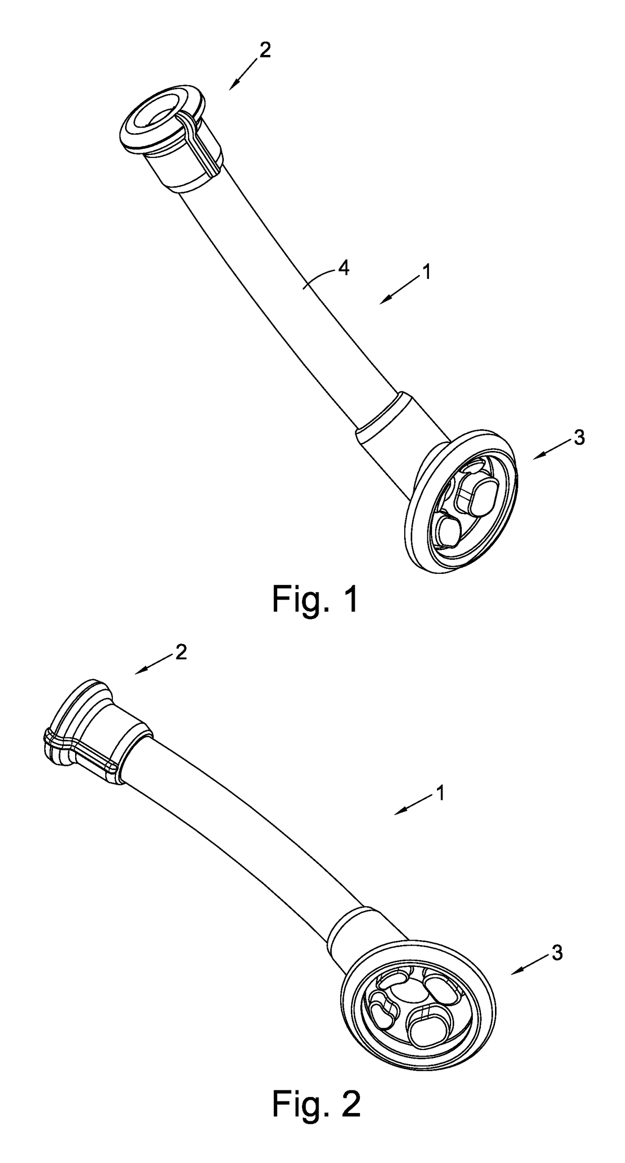
[0039]Referring to the drawings, the obstetric device 1 has certain general features in common with exemplary prior art devices such as those shown in for example US2013 / 0325027 or WO2011 / 058289. For example the devices have in common a proximal end portion 2 and a distal head portion 3 connected at either end of an elongate tube 4 having a longitudinally running hollow bore 5.

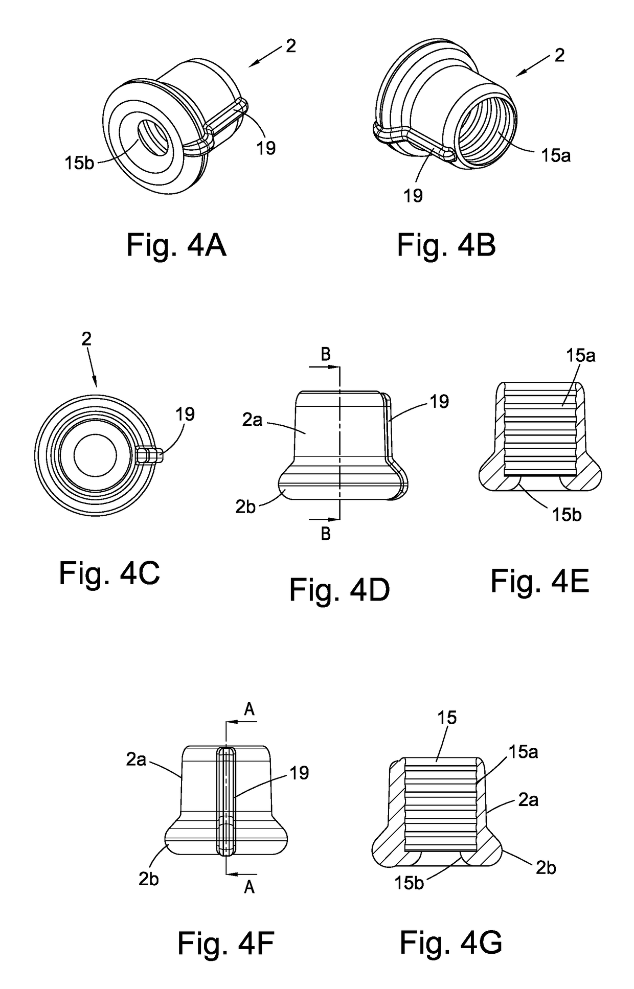
[0040]In accordance with the present invention the proximal end portion 2 and a distal head portion 3 are formed as separate pieces and connected at either end of the elongate tube 4. Each of the distal head piece 3, elongate tube 4, and a proximal end piece 2 are formed of platinum grade silicon 30 / 40 Shore.

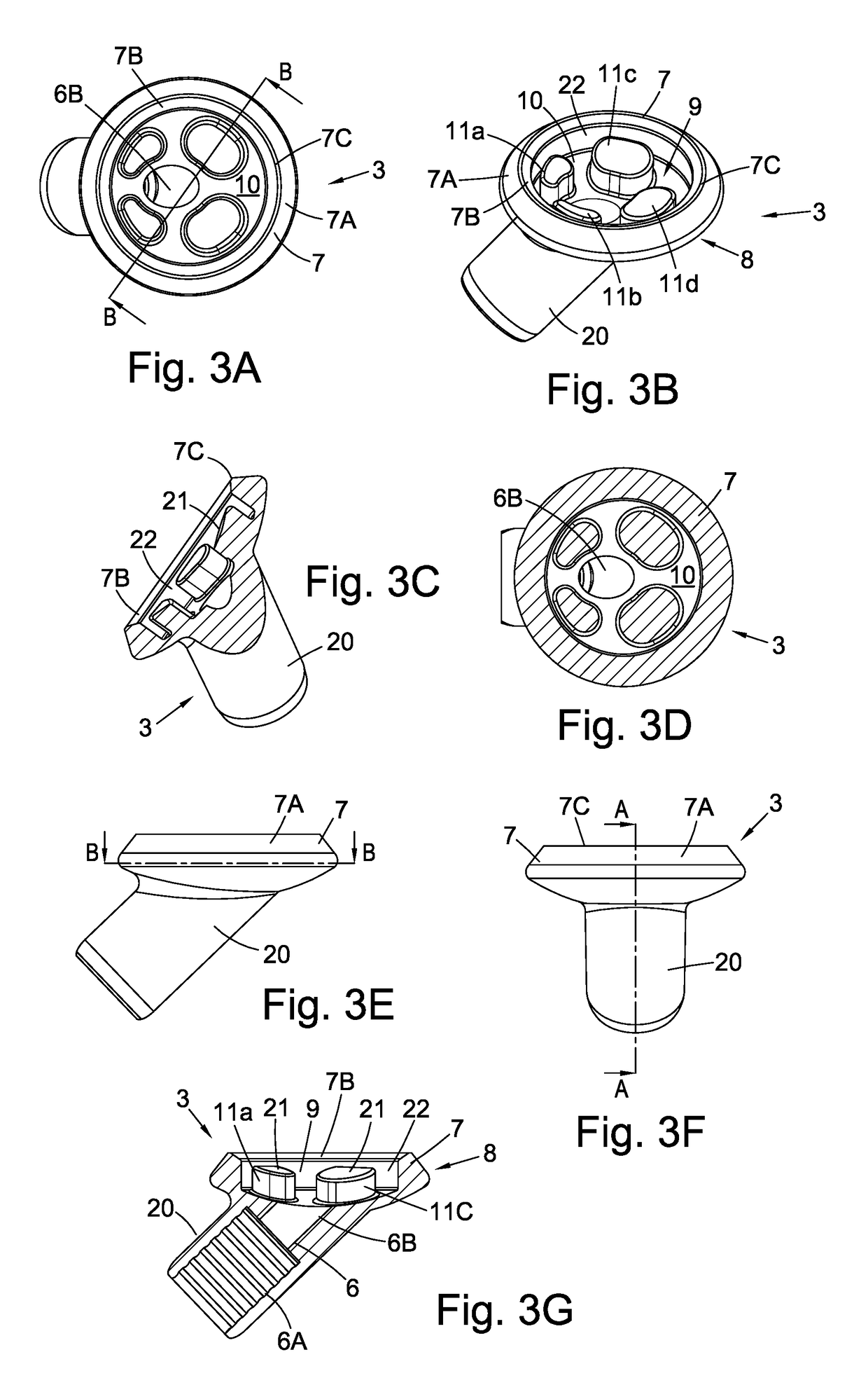
[0041]Referring to FIGS. 3A to 3G, the head portion 3 has a stem 20 internally of which is provided a longitudinally running stepped bore 6 communicating with opposed ends having a wide bore portion 6A and a narrower bore portion 6B. Bore portion 6A has a profiled inner surface arranged to provide a grip f...


PUM


Abstract

An obstetric device has a head piece having a flexible peripheral rim and a floor spaced from the flexible peripheral rim defining a cavity. One or more support lugs extend upwardly from the floor of the cavity; and an air communication aperture is provided in the floor of the cavity. Typically the device is formed a distal end piece having an orientation mark; and a tube interconnecting the head piece and the distal end piece.

Description

BACKGROUND[0001]1. Field[0002]This invention relates generally to an obstetric device, and more particularly to an obstetric device for use in birthing processes particularly birthing processes in which the baby is not delivered via the birthing canal.[0003]2. Related Art[0004]It is not uncommon during the birthing process for a pregnant woman to reach full dilation of the cervix and begin pushing the fetus down through the birth canal only to have the fetus become lodged in the birth canal. Often a vacuum or forceps may be used to further assist the delivery. This may, however, worsen the situation by causing the fetus to become more firmly impacted or lodged in the birth canal without achieving delivery. After attempts of vaginal delivery are abandoned, the delivering physician must deliver the fetus through caesarean section.[0005]During the course of a caesarean section, the fetus must be positioned such that the physician can reach behind the head of the fetus to deliver the ba...

Claims


Application Information

Patent Timeline
Patent Type & Authority Patents(United States)
IPC IPC(8): A61B17/42A61B17/00A61B90/00
CPCA61B17/42A61B2090/0811A61B2017/00455
Inventor TYDEMAN, GRAHAM STEPHEN JOHN
Owner GUYS & ST THOMAS NHS FOUND TRUST
Why Eureka
Try Eureka