
Method for separating a layer from a composite structure

a composite structure and layer technology, applied in the direction of lamination ancillary operations, electrical equipment, chemistry apparatus and processes, etc., can solve the problems of less uniform separation, significant deformation, and more radiation exposure, so as to reduce the variation in actual transmitted energy, reduce the effect of optical interference between incident rays and reflected rays, and limit or avoid optical interactions

Active Publication Date: 2019-03-05
SOITEC SA
View PDF13 Cites 0 Cited by
  • Summary
  • Abstract
  • Description
  • Claims
  • Application Information

AI Technical Summary

Benefits of technology

The disclosed method reduces or prevents optical interference between incident and reflected rays during separation by exfoliation, improving the quality and reproducibility of the separation. This is particularly useful for composite structures with different compositions and sensitive to optical interference. The method maximizes the amount of light energy transmitted to the separation layer during irradiation.

Problems solved by technology

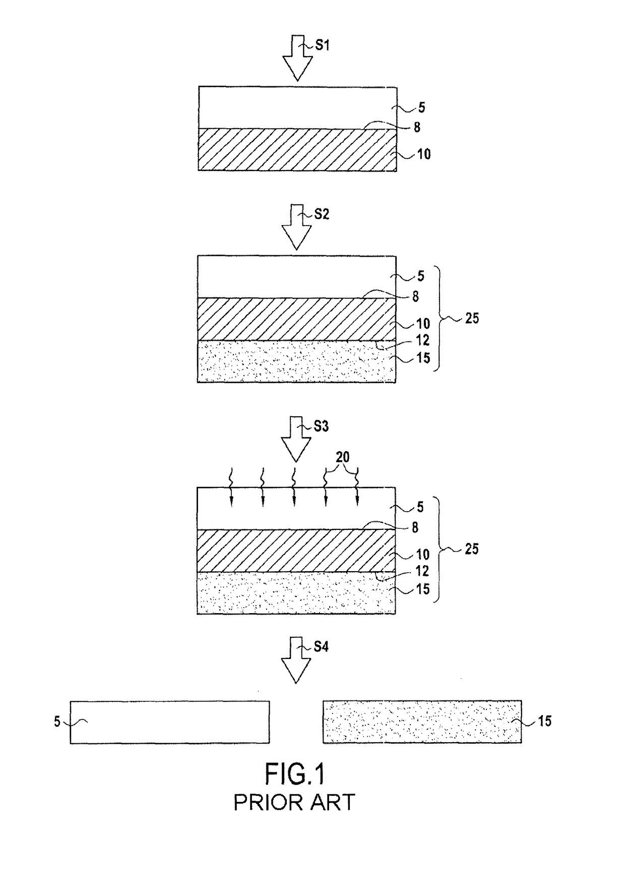
The Applicant has, however, observed that the results can be significantly degraded when this separation method is applied to other compositions of the composite structure 25.
The Applicant has observed large variations in terms of quality of separation by exfoliation as a function of the batches studied and, in general, less uniform separations requiring more exposure to radiation.

Method used


Image

  • Method for separating a layer from a composite structure
  • Method for separating a layer from a composite structure

Examples


Embodiment Construction

[0039]The present disclosure relates to a separation method making it possible to detach or weaken, by exfoliation, a layer to be separated from a composite structure of conventional or unconventional composition.

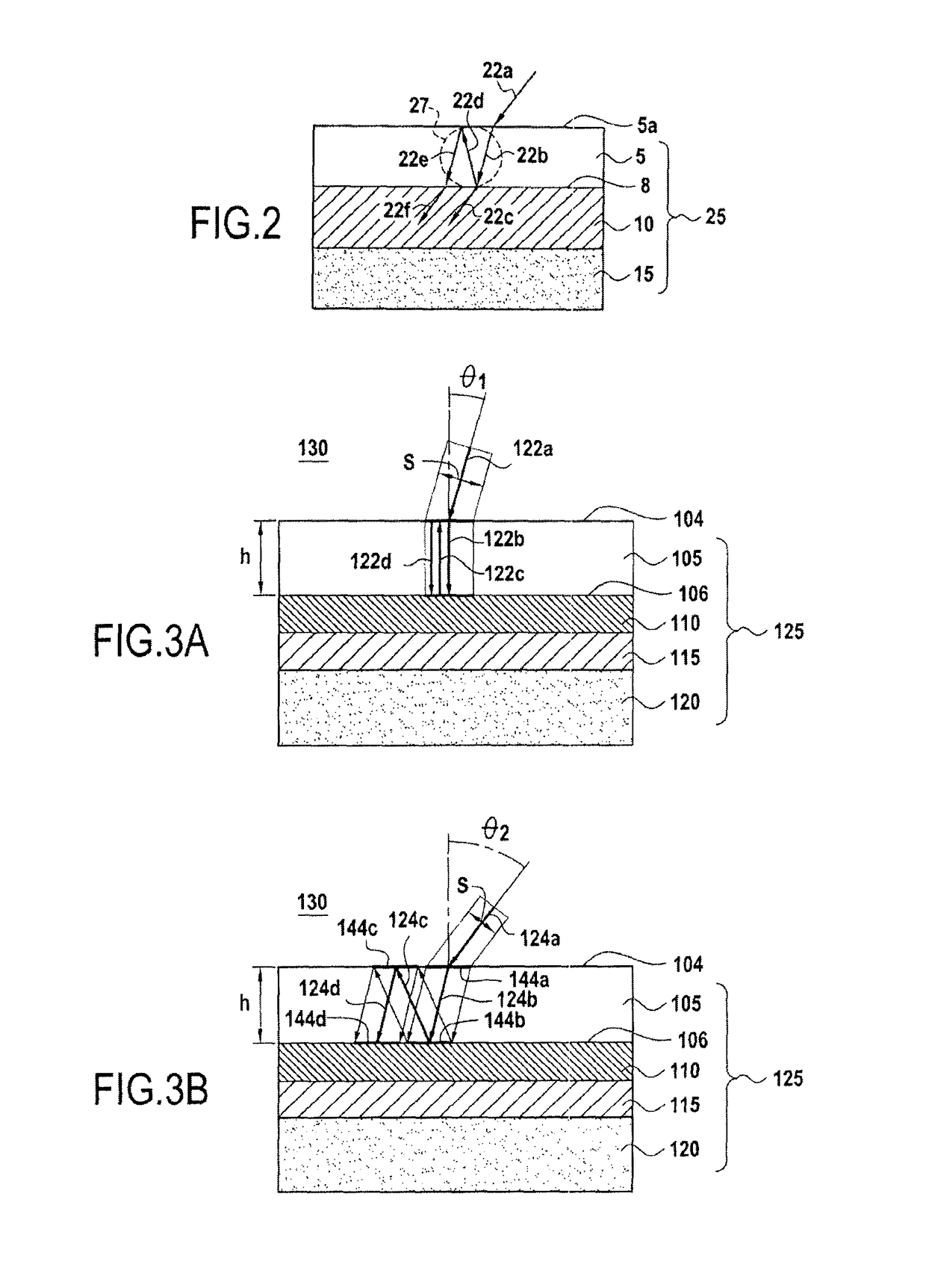
[0040]The Applicant has carried out a study which has made it possible to demonstrate the physical mechanism giving rise to the difficulties encountered for carrying out a method of separation by exfoliation. The study has in particular demonstrated the role of the optical interference occurring in the support substrate during the irradiation of the composite structure.

[0041]This mechanism will now be described with reference to FIG. 2. This figure represents the composite structure 25, as described above, with reference to FIG. 1.

[0042]FIG. 2 represents in particular an incident light ray 22a reaching the exposed surface 5a of the support substrate 5 during the irradiation step S3. As for any light ray encountering a semi-absorbent medium, a part (not represented) of the l...


PUM

PropertyMeasurementUnit
thicknessaaaaaaaaaa
Brewster angle θmaxaaaaaaaaaa

Abstract

The disclosure relates to a method for separating a layer from a composite structure, the structure comprising a composite stack formed from at least a support substrate, which is partially transparent at a determined wavelength, the layer to be separated and a separation layer interposed between the support substrate and the layer to be separated, the method comprising irradiation of the separation layer through the support substrate by means of incident light ray at the determined wavelength in order to induce weakening or separation by exfoliation of the separation layer, the light ray being inclined so as to form an angle of incidence Θ such that θ>θmin, where θmin=sin−1((n1 / n0)sin(tan−1(s / 2h))), n1 and n0, respectively, being the refractive index of the support substrate and the refractive index of the external medium in contact with the support substrate, from which the ray comes, S being the width of the ray and h being the thickness of the support substrate.

Description

CROSS-REFERENCE TO RELATED APPLICATIONS[0001]This application is a national phase entry under 35 U.S.C. § 371 of International Patent Application PCT / IB2012 / 001406, filed Jul. 18, 2012, designating the United States of America and published in English as International Patent Publication WO2013 / 011372 A1 on Jan. 24, 2013, which claims the benefit under Article 8 of the Patent Cooperation Treaty to France Application Serial No. 1158331, filed Sep. 20, 2011, the disclosure of each of which is hereby incorporated herein in its entirety by this reference.BACKGROUND[0002]The disclosure concerns the field of the fabrication of composite (or multilayer) semiconductor structures, and relates more particularly to methods of separation by exfoliation making it possible to detach one or more layers of a composite structure, for example, in the scope of transferring layers from an initial support to a final support.[0003]In the field of the fabrication of composite structures, it is often useful...

Claims


Application Information

Patent Timeline
Patent Type & Authority Patents(United States)
IPC IPC(8): B32B43/00H01L21/762H01L21/00B32B38/10
CPCB32B43/006H01L21/76251H01L21/76254Y10T156/1158B32B2310/0806H01L21/00B32B38/10
Inventor LANDRU, DIDIER
Owner SOITEC SA
Learn More