
Method and apparatus for controlling transmission signal for disaster scene communication system

a communication system and disaster scene technology, applied in the field of public service process, can solve the problems of reducing communication distance, deteriorating data reception success rate, and difficulty in controlling and managing the activities of emergency responders, and achieves reliable wireless communication performance, sufficient communication distance, and reliable communication environment.

Inactive Publication Date: 2019-03-05
ELECTRONICS & TELECOMM RES INST
View PDF8 Cites 1 Cited by
  • Summary
  • Abstract
  • Description
  • Claims
  • Application Information

AI Technical Summary

Benefits of technology

The patent text describes a solution to improve wireless communication in emergency situations by controlling the transmission power of signals. This approach helps to avoid signal interference and improve overall communication performance. The patent also outlines a method and apparatus for overcoming communication obstacles and securing a reliable wireless communication distance in disaster scenes.

Problems solved by technology

Under circumstances when a disaster occurs indoor, wireless signals become attenuated while being transmitted due to various obstacles, which reduces a communication distance and deteriorates a data reception success rate.
Accordingly, even though emergency responders are equipped with emergency response equipment, there is a difficulty in controlling and managing the activities of emergency responders.
However, when the transmission power of signals is simply enhanced, signals communicated between the emergency response equipment distributed in various locations are likely to be interfered, resulting in deterioration of an overall communication performance of the emergency response equipment.

Method used


Image

  • Method and apparatus for controlling transmission signal for disaster scene communication system
  • Method and apparatus for controlling transmission signal for disaster scene communication system
  • Method and apparatus for controlling transmission signal for disaster scene communication system

Examples


Embodiment Construction

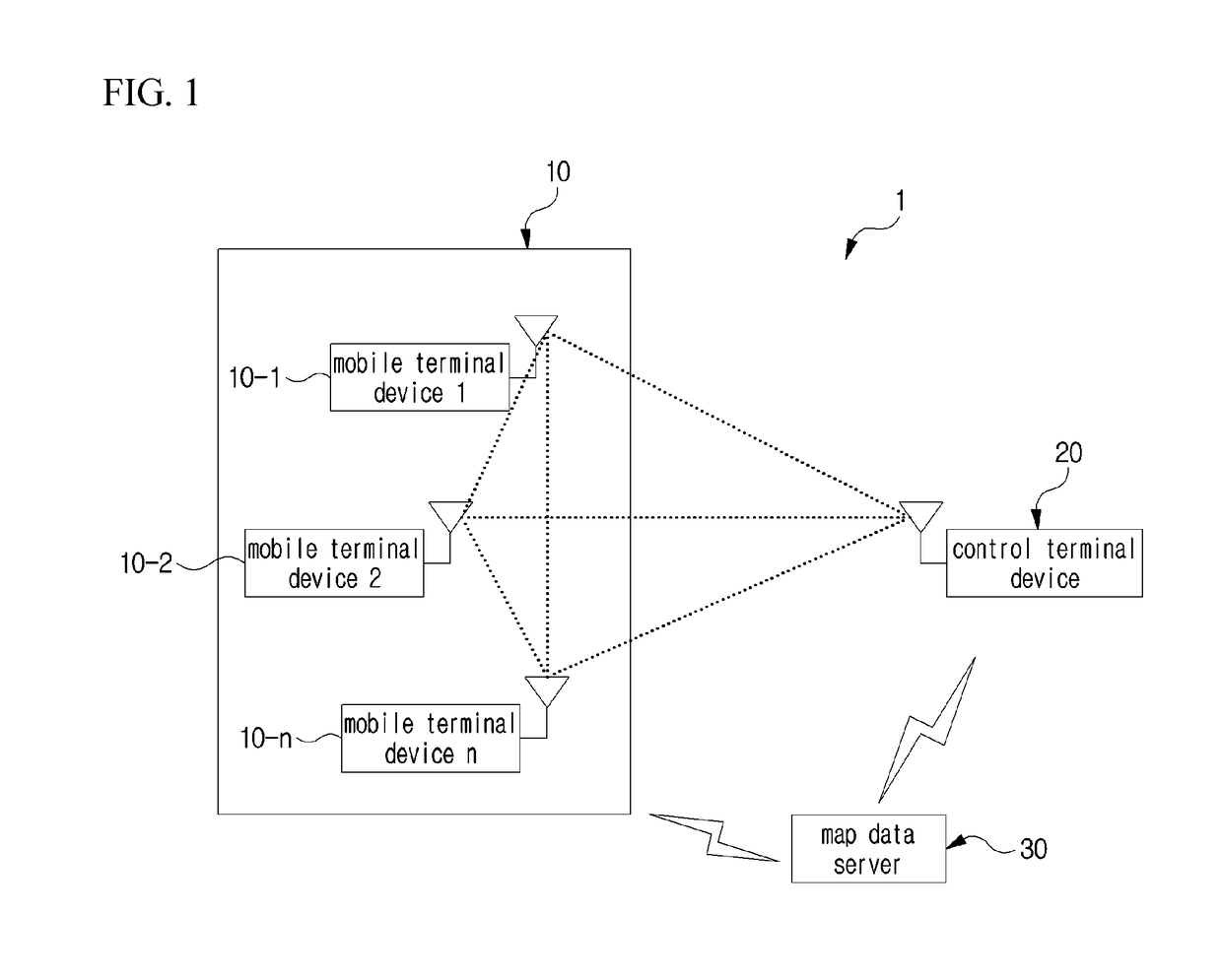
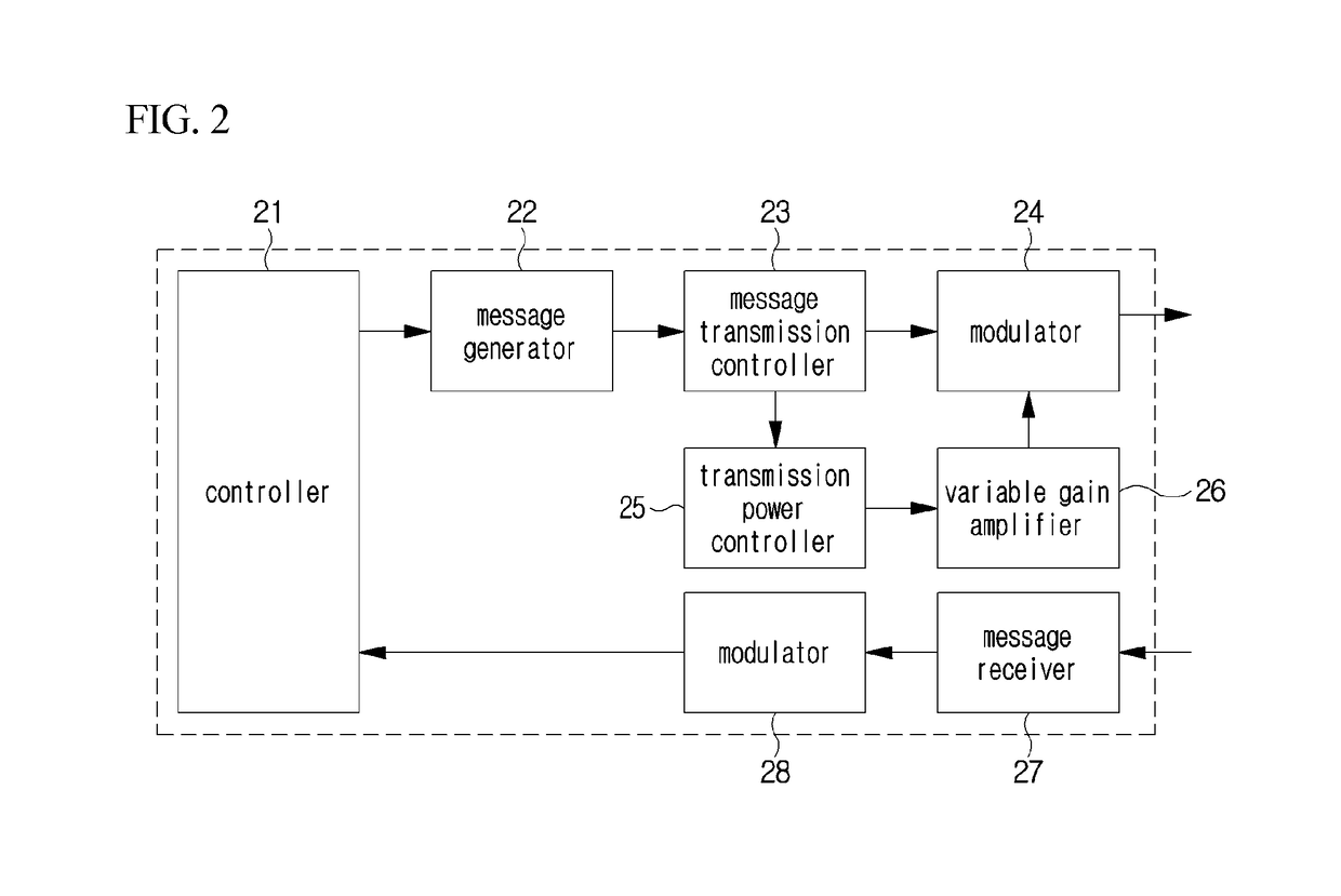
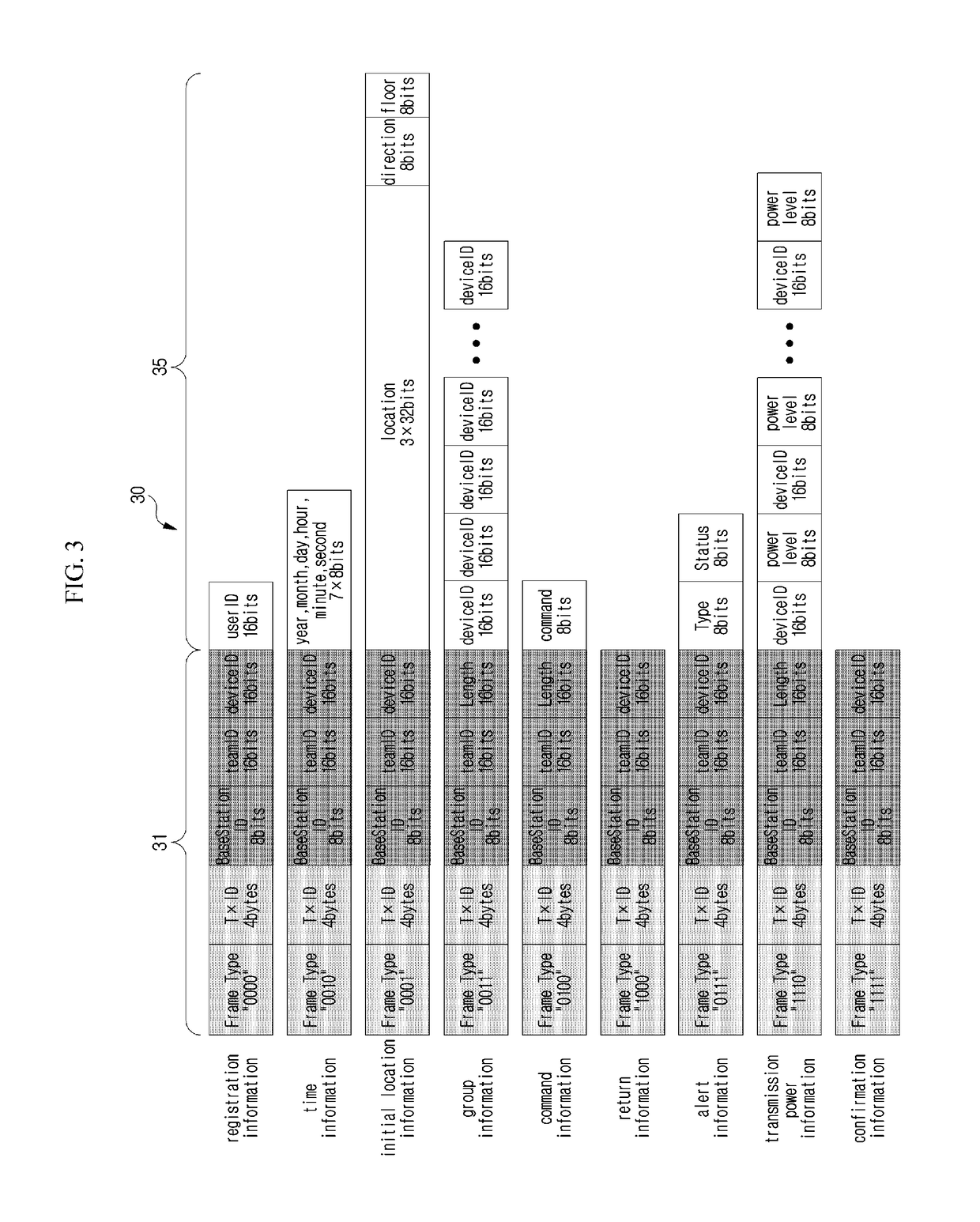
[0030]Hereinbelow, exemplary embodiments of the present invention will be described in detail with reference to the accompanying drawings such that the invention can be easily embodied by those ordinarily skilled in the art to which this invention belongs. However, the present disclosure may be embodied in various forms and should not be construed as being limited to the exemplary embodiments disclosed herein.

[0031]Further, when it is determined that the detailed description of the known art related to the present invention might obscure the gist of the present invention, the detailed description thereof will be omitted. Further, in the drawings, parts that are not related to the present disclosure are omitted, and like parts are denoted by like reference numerals.

[0032]In the present disclosure, it will be understood that when an element is referred to as being “coupled” or “connected” to another element, it can be directly coupled or connected to the other element or intervening e...


PUM


Abstract

A method and apparatus for controlling a transmission signal for a disaster scene communication system. The method includes determining a type of a transmission message transmitted to a mobile terminal device by a control terminal device of the disaster scene communication system, determining a criticality level of the transmission message corresponding to the type of the transmission message, determining an initial distance between the control terminal device and the mobile terminal device by checking initial location information of the mobile terminal device, setting an initial transmission power in consideration of the criticality level of the transmission message corresponding to the type of the transmission message and the initial distance between the mobile terminal device and the control terminal device, and controlling a current transmission power based on the initial transmission power.

Description

CROSS REFERENCE TO RELATED APPLICATION[0001]The present application claims priority to Korean Patent Application No. 10-2017-0170532, filed Dec. 12, 2017, the entire content of which is incorporated herein for all purposes by this reference.BACKGROUND OF THE INVENTION1. Field of the Invention[0002]The present disclosure relates to a public service process and more particularly to a method and apparatus for transmitting and receiving a wireless signal to and from an emergency management system.2. Description of Related Art[0003]Generally, in case an emergency such as a natural disaster or a fire occurs, there are emergency response organizations to provide countermeasures to such an emergency. For example, the police, the army, the fire department, voluntary work groups, and various similar organizations are emergency response organizations.[0004]When a disaster or emergency is reported to an emergency response organization within an administrative area in which the disaster or emerg...

Claims


Application Information

Patent Timeline
IPC IPC(8): H04W4/90H04W52/28H04W52/52H04W4/12H04W64/00
CPCH04W4/90H04W52/283H04W52/52H04W4/12H04W64/006H04W52/281H04W4/023H04W4/08H04W52/28H04W52/48
Inventor SON, KYO HOONBAE, MYUNG NAMLEE, KANG BOKLEE, HYE SUNJEONG, MIN GIHONG, SANG GI
Owner ELECTRONICS & TELECOMM RES INST
Learn More