Arrangement of a door and cavity for an article of furniture

a technology for furniture and wing accessories, applied in the direction of door/window fittings, wing accessories, wing arrangements, etc., can solve the problem that the operator has to exert a large physical effort to handle the furniture doors

Active Publication Date: 2019-03-12
JULIUS BLUM GMBH
View PDF40 Cites 15 Cited by
  • Summary
  • Abstract
  • Description
  • Claims
  • Application Information

AI Technical Summary

Benefits of technology

[0005]According to the invention, the arrangement includes a mechanical drive device for moving the furniture door between a, preferably fully, countersunk position within the cavity and a position outside of the cavity. In this way, moving the furniture door into the cavity and out of the cavity, respectively, can be significantly facilitated.
[0008]It has further turned out beneficial when the drive device includes a control curve for controlling a movement of the furniture door between the, preferably fully, countersunk position within the cavity and the position outside of the cavity. The provision of such a control curve has the advantage that the drive force exerted by the drive device can be transmitted to the furniture door according to a predetermined movement pattern in a metered manner. In this way, particularly harmonic movement sequences can be realized, for example in such a way that the furniture door can initially be driven, starting from the, preferably fully, countersunk position within the cavity with a high force and is then being braked and eventually reaches the position outside of the cavity with less speed. In this way, injuries of persons near the cavity as well as damages of a possible damping device for dampening the movement of the furniture door immediately before reaching the position outside of the cavity are prevented.
[0009]An advantageous development of this embodiment lies in the fact that the control curve can be adapted to different depths of the cavity, and the control curve, for this purpose, is composed of at least two segments which are adjustable relative to one another. In this case, the same control curve can always be used for cavities having a different depth, whereby the manufacturing costs can be reduced.
[0013]It has also turned out to be beneficial when the control element, in the mounting position of the drive device and when the furniture door is arranged in the, preferably fully, countersunk position, assumes the highest point or the lowest point of the control curve.
[0014]Beneficial developments of the invention lie in the fact that the drive device, when the furniture door is arranged in the, preferably fully, countersunk position within the cavity, exerts a driving force to the furniture door, and / or the drive device, when the furniture door is arranged outside of the cavity, exerts a restraining force to the furniture door. In the first case, the furniture door, when being located in the, preferably fully, countersunk position within the cavity, can be moved out of the cavity very easily. In the second case, an unintentional pushing-in movement into the cavity at an early stage can be prevented.
[0015]In addition, the arrangement can include a locking device for releasably locking the furniture door in the preferably fully, countersunk position within the cavity, and the locking device can be unlocked, preferably by overpressing the furniture door into an overpressing position which lies behind the, preferably fully, countersunk position. Such locking devices are basically known in the state of art, however not in conjunction with the releasable locking of a furniture door within a cavity. The provision of such a locking device is, in particular, advantageous when the furniture door is to be safely stored within the cavity and the drive device exerts at least a driving force in a direction towards the position outside of the cavity.

Problems solved by technology

A problematic issue with the arrangements according to the state of art is the fact, in particular with heavy furniture doors, for example fold-sliding doors which are composed of a plurality of door wings, that the handling of the furniture doors requires a high physical effort of the operator, in particular in the case when the furniture doors are to be stored within the cavity.

Method used


Image

  • Arrangement of a door and cavity for an article of furniture
  • Arrangement of a door and cavity for an article of furniture
  • Arrangement of a door and cavity for an article of furniture

Examples


Embodiment Construction

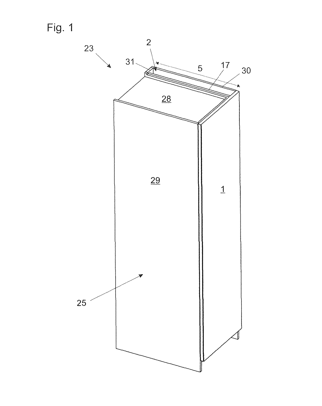
[0028]In particular, FIG. 1 shows a first item of furniture 23 in the form of a cupboard which includes a furniture carcass (furniture body) 25 which is composed of a multiple of side walls 29, 17 and 30 which are arranged in parallel relationship relative to one another, a rear wall which includes a partial section 31, the cover plate 28 and a base plate 32 (see FIG. 2c for example), and a furniture door 1 by way of which the item of furniture 23 can be closed. The side walls 17 and 30 being spaced from one another and the partial section 31 of the rear wall represent limiting surfaces for defining a chamber-formed cavity 2 of the furniture body 25. The width of the side walls 17 and 30 and the cupboard 23, respectively, define the depth 5 of the cavity 2.

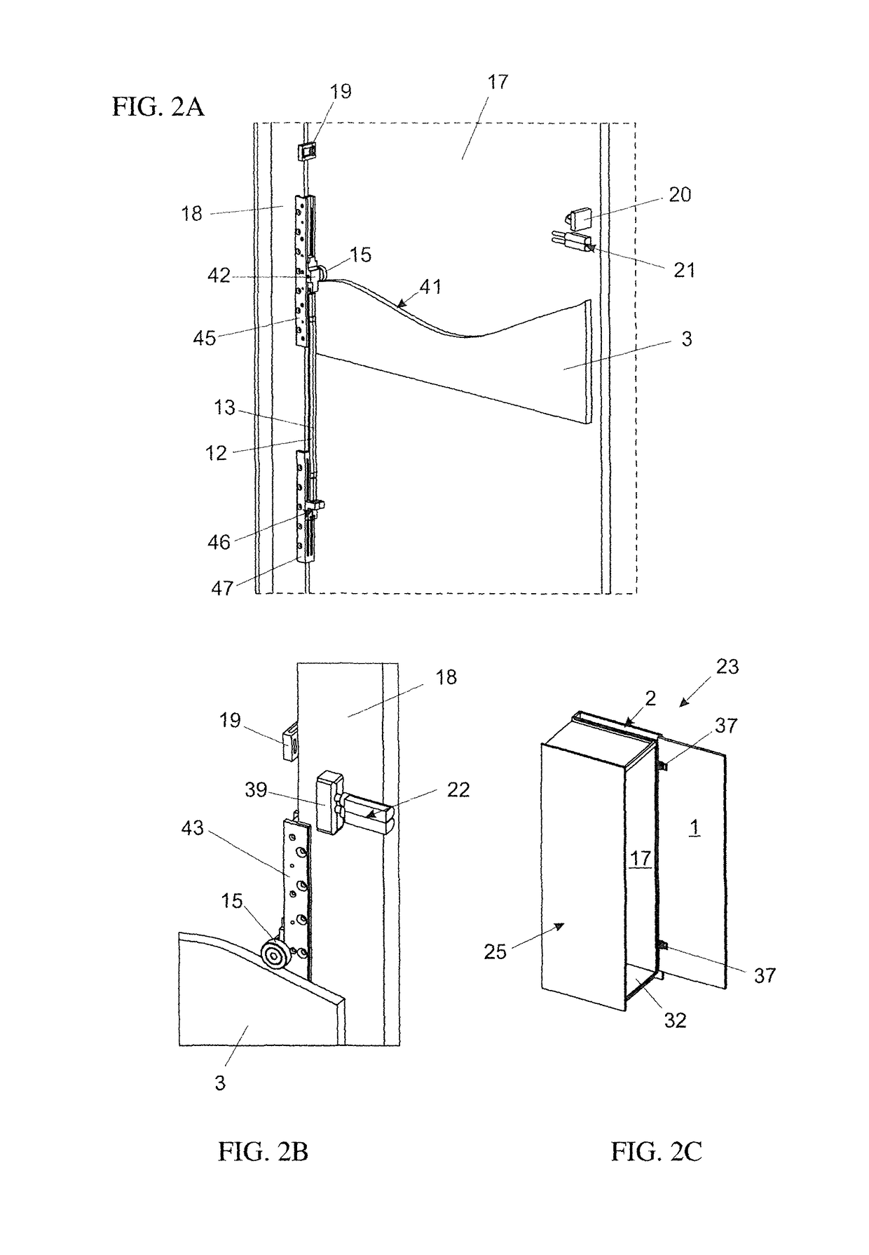
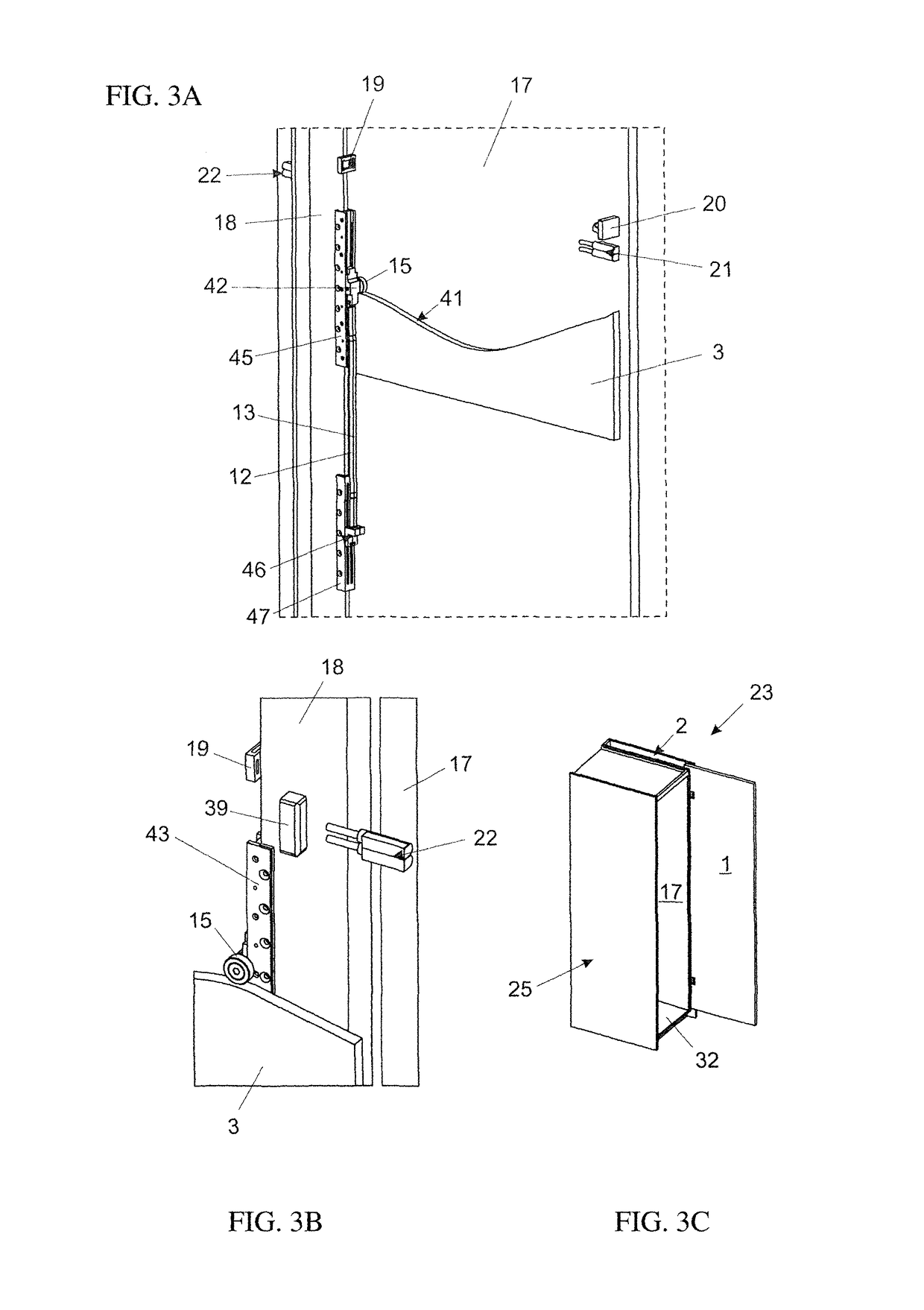
[0029]The furniture door 1 is fastened to a base fastening element 18 by hinges 37, wherein the base fastening element 18, as shown in the following figures, is operatively connected to the drive device.

[0030]As shown in particula...


PUM


Abstract

An arrangement has a furniture door, in particular a fold-sliding-door, and a chamber-formed cavity for accommodating the furniture door. The arrangement includes a mechanical drive device for moving the furniture door between a countersunk position within the cavity and a position outside of the cavity. The drive device is configured so as to move the furniture door, starting from the countersunk position within the cavity into the position outside of the cavity.

Description

BACKGROUND OF THE INVENTION[0001]The invention relates to an arrangement having a furniture door, in particular a fold-sliding door, and a, in particular chamber-formed, cavity for accommodating the furniture door.[0002]Such arrangements are known, for example, from EP 0 433 726 B1 or DE 43 08 196 A1.[0003]A problematic issue with the arrangements according to the state of art is the fact, in particular with heavy furniture doors, for example fold-sliding doors which are composed of a plurality of door wings, that the handling of the furniture doors requires a high physical effort of the operator, in particular in the case when the furniture doors are to be stored within the cavity.SUMMARY OF THE INVENTION[0004]It is therefore an object of the present invention to provide an improved arrangement with respect to the prior art, thereby avoiding the problems discussed above.[0005]According to the invention, the arrangement includes a mechanical drive device for moving the furniture doo...

Claims


Application Information

Patent Timeline
Patent Type & Authority Patents(United States)
IPC IPC(8): E05D15/58E06B3/50E05D15/26E06B3/48
CPCE05D15/58E06B3/5045E06B3/482E05Y2900/20E05Y2900/212E05D15/264E05F1/08E05F5/06E05F1/16
Inventor GABL, DOMINIK
Owner JULIUS BLUM GMBH
Why Eureka
Try Eureka