Rail system for a drawer

a rail system and drawer technology, applied in the field of drawer side walls, can solve problems such as lack of stability, and achieve the effect of high stability

Active Publication Date: 2019-03-19
JULIUS BLUM GMBH
View PDF41 Cites 1 Cited by
  • Summary
  • Abstract
  • Description
  • Claims
  • Application Information

AI Technical Summary

Benefits of technology

[0003]Therefore the object of the invention is to provide a drawer side wall which is improved over the state of the art. In particular, the invention seeks to achieve a higher level of stability in the event of a force acting by way of the drawer front panel.

Problems solved by technology

Particularly in the case of high drawer front panels or high front fitment members, that leads to a lack of stability.

Method used


Image

  • Rail system for a drawer
  • Rail system for a drawer
  • Rail system for a drawer

Examples


Embodiment Construction

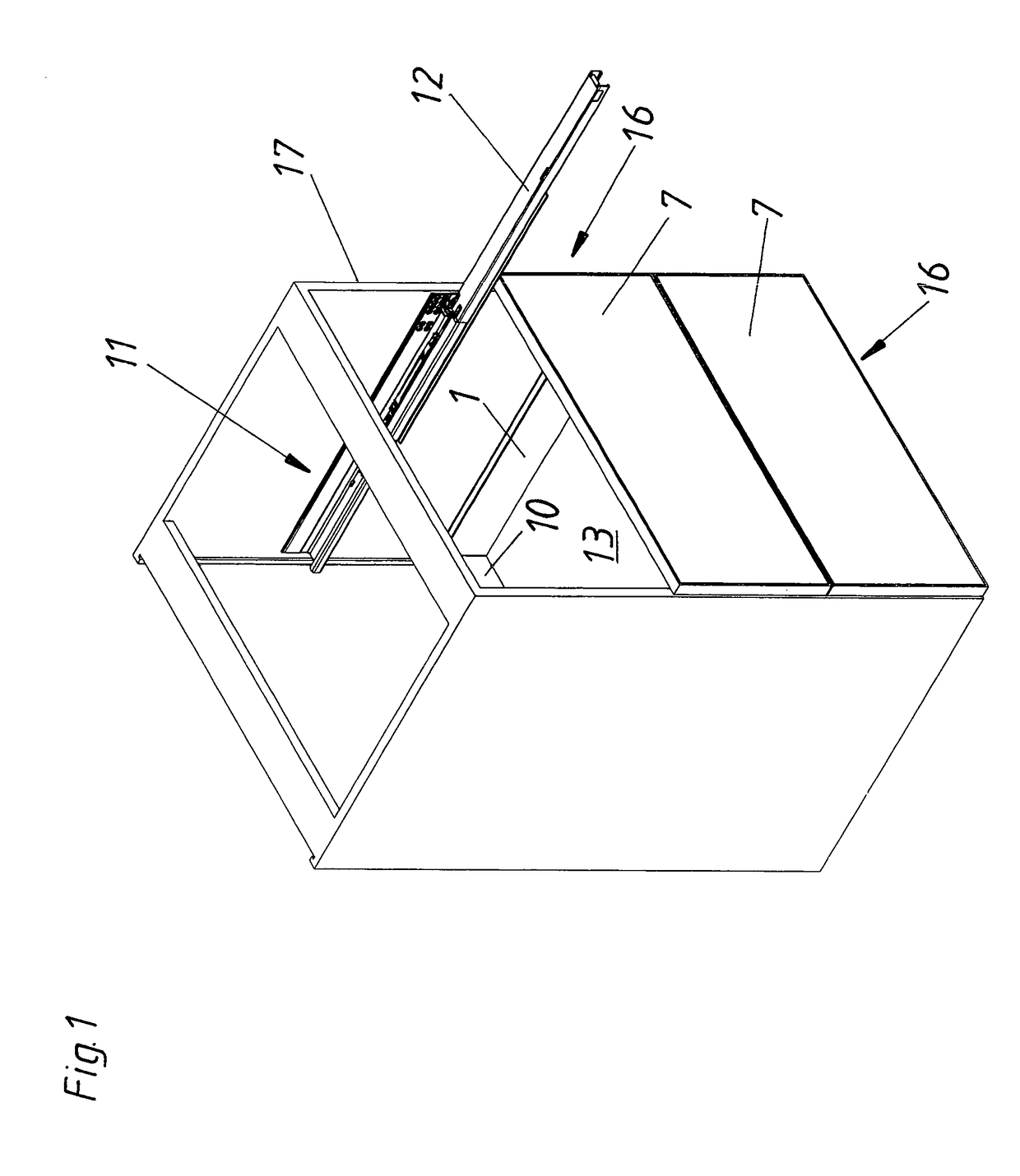
[0026]FIG. 1 is a perspective view of an article of furniture, in which drawers 16 are mounted displaceably relative to a furniture carcass 17 by drawer extension guides 11. A drawer 16 respectively includes two drawer side walls 1, a drawer rear wall 10, a drawer front panel 7 and a bottom 13. The bottom 13 of a drawer 16 typically has at the underside two openings for receiving a container rail 4 (not shown here), with which the drawer 16 is to be connected to the extension rails 12 of two drawer extension guides 11 fixed to the furniture carcass 17 at left and right.

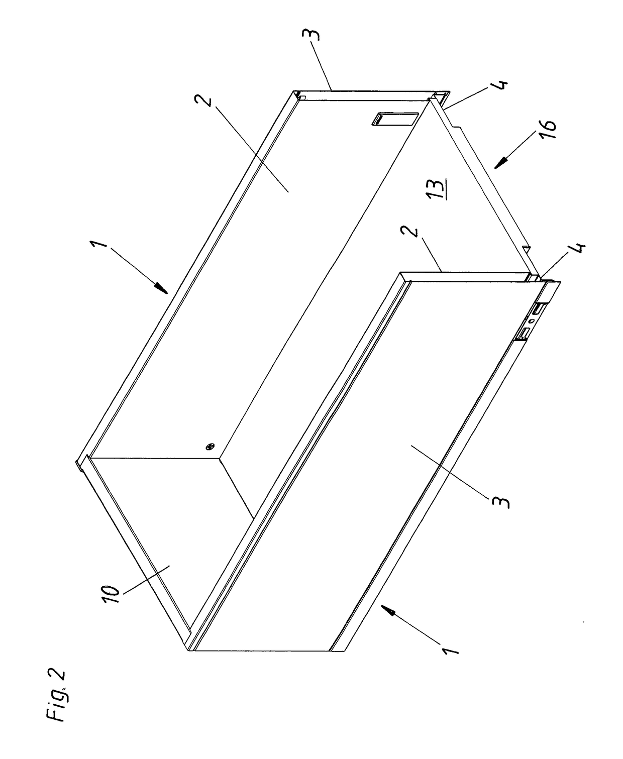
[0027]FIG. 2 shows a perspective view of a drawer 16 with drawer front panel 7 removed. The side walls 1 of the drawer 16 respectively include an inner wall 2 and an outer wall 3 connected to the respective inner wall 2. At the underside, the bottom 13 of the drawer 16 has two openings which are substantially positively lockingly clad by two container rails 4. The container rails 4 serve for fixing the drawer 16 to th...


PUM


Abstract

A drawer side wall having an inner wall and an outer wall which can be connected to the inner wall. A container rail is provided, and the drawer side wall can be connected to the container rail. An upwardly protruding front projection with a device for attachment of a drawer front panel is arranged on the container rail, and the inner wall is directly firmly connected to the container rail in a lower region. The front projection is directly firmly connected, preferably by welding, to the inner wall in an upper region of the inner wall.

Description

BACKGROUND OF THE INVENTION[0001]The invention concerns a drawer side wall having an inner wall and an outer wall connectable to the inner wall, and the drawer side wall is connectable to a container rail. Arranged on the container rail is an upwardly projecting front fitment member with a device for fixing a drawer front panel.[0002]Drawer side walls are frequently arranged on or fixed to container rails. Two container rails are then typically inserted into suitable openings in the underside of the bottom of a drawer and serve to connect the drawer to moveable extension rails of two drawer extension guides arranged on a furniture carcass. In the case of container rails known in the state of the art, a front fitment member and a rear fitment member are frequently respectively arranged thereon, the fitment members serving to fix a drawer front panel and drawer rear wall respectively (for example EP 1 084 655 A1, EP 1 157 636 A1). Forces which are usually applied to that arrangement b...

Claims


Application Information

Patent Timeline
Patent Type & Authority Patents(United States)
IPC IPC(8): A47B88/40A47B88/427A47B88/90
CPCA47B88/941A47B88/40A47B88/427A47B2210/02A47B2088/902
Inventor GASSER, INGO
Owner JULIUS BLUM GMBH
Why Eureka
Try Eureka