Piston pump assembly comprising piston with variable stroke and vehicle braking system comprising the same

a technology of variable stroke and piston, which is applied in the direction of piston pumps, positive displacement liquid engines, liquid fuel engines, etc., can solve the problems of high brake fluid viscosity, difficult and costly manufacturing of the drive shaft described in u.s. patent no 8,322,997b2, and achieve low cost and high stability

Active Publication Date: 2020-09-01
HL MANDO CORP
View PDF16 Cites 0 Cited by
  • Summary
  • Abstract
  • Description
  • Claims
  • Application Information

AI Technical Summary

Benefits of technology

[0011]It is an aspect of the present disclosure to provide a piston pump assembly with a variable stroke to provide a high level of stability under a hydraulic braking system and to be manufactured at low cost.
[0022]Further, the cam may be particularly simple to manufacture and the assembly may have a compact design by integrally forming the first cam portion and the second cam portion. The cam may comprise or may be made of metal or a high grade plastic material. For example, the cam may extend in a direction perpendicular to the piston axis. The first cam portion and the second cam portion may then be formed in different sections of the cam along the direction perpendicular to the piston axis. Similarly, the cam may extend in a direction parallel to the axis of rotation. The first cam portion and the second cam portion may then be formed in different sections of the cam along the direction parallel to the axis of rotation.
[0023]Further, movement of the cam relative to the piston axis may be facilitated if the cam comprises a transition portion joining the first cam portion and the second cam portion, wherein an outer surface of the transition portion provides a continuous transition between an outer surface of the first cam portion and an outer surface of the second cam portion. In particular, the transition portion may be formed in one piece with the first cam portion and the second cam portion.

Problems solved by technology

For example, during the cold-start phase of the vehicle the temperature of the brake fluid is typically low, resulting in a high viscosity of the brake fluid.
On the other hand, friction and shear stress acting on the brake fluid typically may cause the viscosity of the brake fluid to decrease over time.
However, the drive shaft described in U.S. Pat. No. 8,322,997B2 may be difficult and costly to manufacture.

Method used


Image

  • Piston pump assembly comprising piston with variable stroke and vehicle braking system comprising the same
  • Piston pump assembly comprising piston with variable stroke and vehicle braking system comprising the same
  • Piston pump assembly comprising piston with variable stroke and vehicle braking system comprising the same

Examples


first embodiment

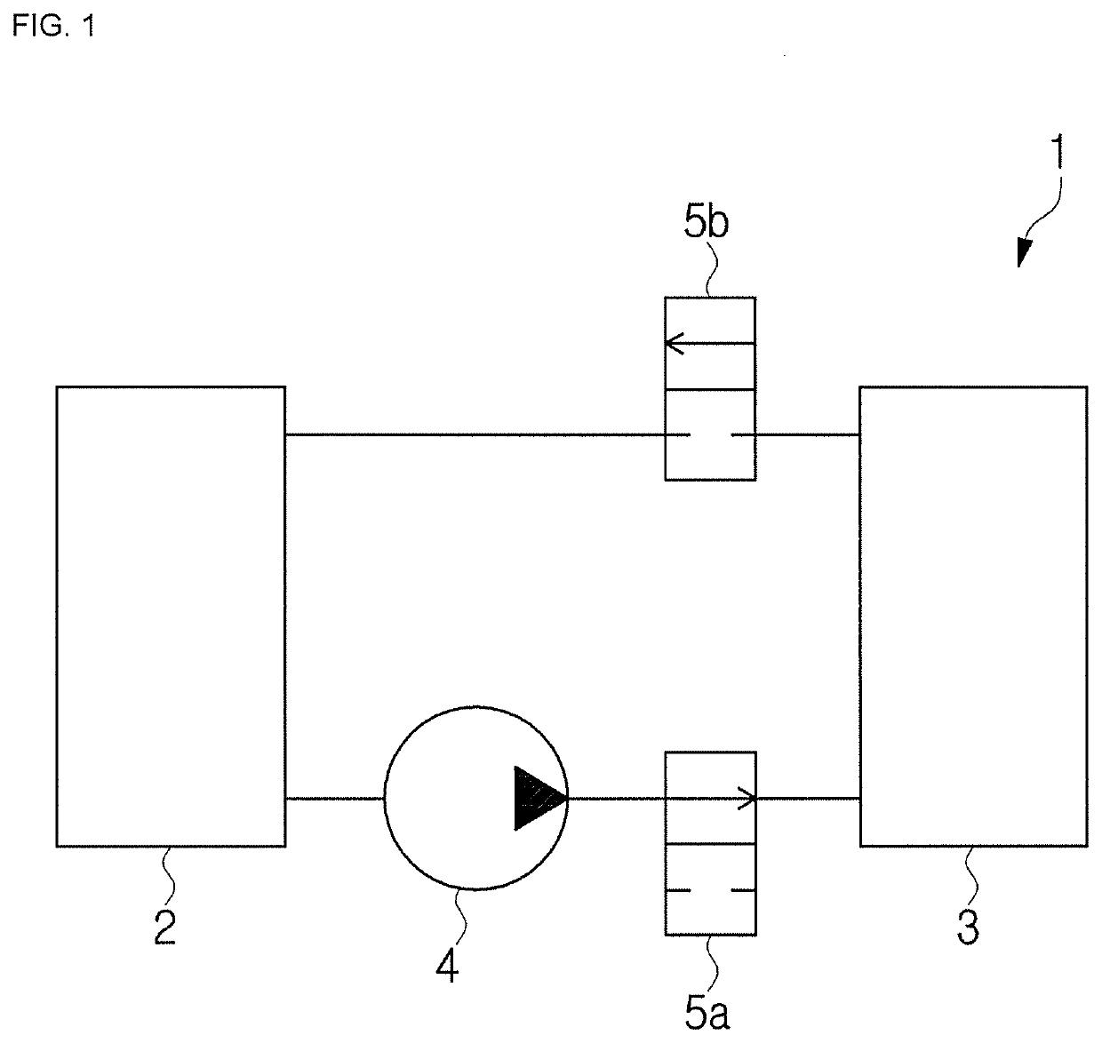
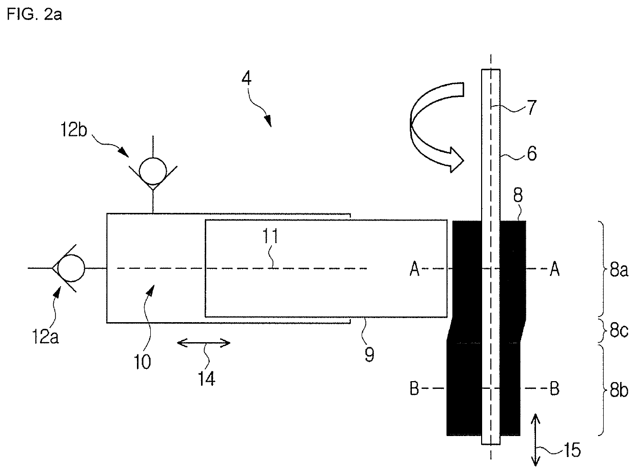
[0044]FIG. 2a schematically depicts a sectional view of the piston pump assembly 4 of FIG. 1 according to a Here and in the following recurring features are designated by the same reference signs. The piston pump assembly 4 comprises a drive shaft 6 defining an axis of rotation 7 of the drive shaft 6, a cam 8 disposed on the drive shaft 6, and a piston 9 partially disposed within a pump cylinder 10 and configured to reciprocate within the pump cylinder 10 along a piston axis 11. The piston pump assembly 4 typically further includes a motor, for example an electric motor (not shown), configured to drive the drive shaft 6. The drive shaft 6 and the piston 9 are configured such that the axis of rotation 7 and the piston axis 11 are arranged perpendicular to one another. For example, the axis of rotation 7 and the piston axis 11 may intersect one another.

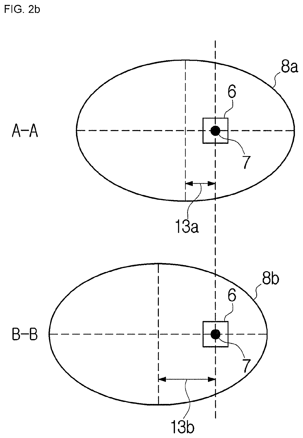
[0045]The cam 8 extends along the axis of rotation 7. The cam 8 comprises a first cam portion 8a extending along a first axial sectio...

second embodiment

[0054]FIGS. 3a to 3c schematically depict sectional views of the piston pump assembly 4 of FIG. 1 according to a The drawing plane of FIGS. 3a to 3c is arranged perpendicular to the drawing plane of FIG. 2a. In particular, in FIGS. 3a to 3c the piston axis 11 is arranged perpendicular to the drawing plane of FIGS. 3a to 3c. For brevity, only the differences between the embodiment shown in FIGS. 3a to 3c and the embodiment shown in FIGS. 2a and 2b will be described in detail.

[0055]The piston pump assembly 4 according to FIGS. 3a to 3c comprises a housing 16. The housing 16 may be made of metal or of a high grade plastic. However, it is understood that the housing 16 may be made of other materials. The drive shaft 6 is rotatably mounted in the housing 16, for example by one or more bearings. A cam chamber 17 is formed inside the housing 16. The drive shaft 6 extends through the cam chamber 17. The cam 8 is movably disposed within the cam chamber 17. In particular, the cam 8 is mounte...

third embodiment

[0063]FIGS. 4a and 4b schematically depict sectional views of the piston pump assembly 4 of FIG. 1 according to a FIG. 4c illustrates a perspective view of the cam 8 shown in FIGS. 4a and 4b. Again, the drawing plane of FIGS. 4a and 4b is arranged perpendicular to the drawing plane of FIG. 2a so that the piston axis 11 is arranged perpendicular to the drawing plane of FIGS. 4a and 4b. For brevity, only the differences between the embodiment shown in FIGS. 4a and 4b and the embodiment shown in FIGS. 3a to 3c will be described in detail.

[0064]The embodiment of the piston pump assembly 4 according to FIGS. 4a and 4b differs from the embodiment of the piston pump assembly 4 according to FIGS. 3a to 3c in that the cam 8 is fixed to the drive shaft 6. For example, the cam 8 may be welded or bolted to the drive shaft 6. However, it is understood that the cam 8 may be fixed to the drive shaft 6 using other means. In the embodiment depicted in FIGS. 4a and 4b both the drive shaft 6 and the ...


PUM


Abstract

The present disclosure relates to a piston pump assembly comprising a piston with a variable stroke and to a hydraulic braking system comprising the same. The piston pump assembly comprises at least: a rotatable drive shaft defining an axis of rotation of the rotatable drive shaft; a cam disposed on the drive shaft; and the piston biased toward the cam and configured to reciprocate along a piston axis for displacing a hydraulic fluid. The cam is movable relative to the piston axis and is selectively placed in one of a first position at a first distance from the piston axis and a second position at a second distance from the piston axis; and wherein the cam comprises at least two portions each of which has, at a given position of the cam relative to the piston axis, a different non-circular cross section in a plane perpendicular to the axis of rotation and / or a different eccentricity with respect to the axis of rotation, the at least two portions of the cam comprising at least a first cam portion having a first non-circular cross section and / or a first eccentricity, and a second cam portion having a second non-circular cross section and / or a second eccentricity.

Description

CROSS-REFERENCE TO RELATED APPLICATION(S)[0001]This application claims priority to and the benefit of German Patent Application No. 102017206723.3, filed on Apr. 21, 2017 in the German Intellectual Property Office, the disclosure of which is incorporated herein by reference in its entirety.BACKGROUND1. Technical Field[0002]The present disclosure relates to a piston pump assembly comprising a piston with a variable stroke and to a vehicle braking system comprising the same.2. Description of the Related Art[0003]Hydraulic braking systems usually include a hydraulic control unit (HCU) for the regulation of the brake fluid within the two brake circuits. Piston pumps are used to control the pressure in the wheel brake cylinders, empty the low pressure accumulators, and to provide brake fluid in special cases, especially for functional safety reasons such as when the driver does not act.[0004]Piston pumps are mostly driven by a common eccentric unit configured to transform a rotational mo...

Claims


Application Information

Patent Timeline
Patent Type & Authority Patents(United States)
IPC IPC(8): F04B9/04F04B19/22F04B1/0413F04B1/053F04B49/12B60T8/40F16D65/18B60T13/16
CPCF04B49/125F04B9/042F16D65/18F04B1/053B60T13/168F04B19/22B60T8/4031F04B1/0413F04B49/126B60T8/4018B60T8/4059F04B2205/10F04B2207/03B60T13/14F04B9/04F04B17/03F04B53/10F04B53/14F04B53/16F05B2210/11
Inventor KUENKEL, AXELLEITER, RALF
Owner HL MANDO CORP
Why Eureka
Try Eureka