
Stable, high-speed marine vessel

a high-speed, marine technology, applied in special-purpose vessels, vessel construction, transportation and packaging, etc., can solve the problems of static-lift craft developing a substantial amount of dynamic drag, static-lift craft becoming relatively inefficient, and type of craft not being able to operate, so as to achieve a greater amount of speed and a higher level of stability

Inactive Publication Date: 2007-08-14
LOCKHEED MARTIN CORP
View PDF11 Cites 0 Cited by
  • Summary
  • Abstract
  • Description
  • Claims
  • Application Information

AI Technical Summary

Benefits of technology

[0006]The present invention provides a marine vessel that provides a greater amount of speed than most static-lift vessels yet also provides a higher level of stability than most dynamic-lift craft.
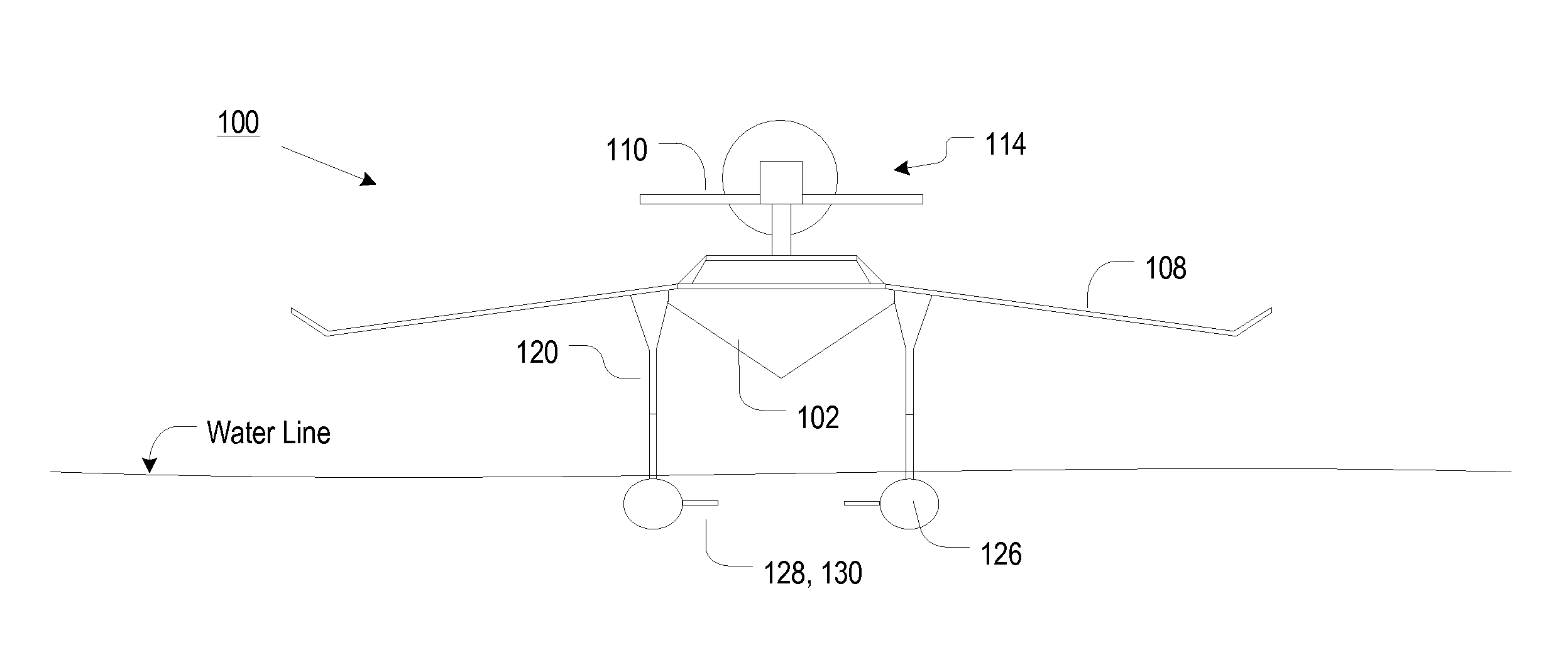
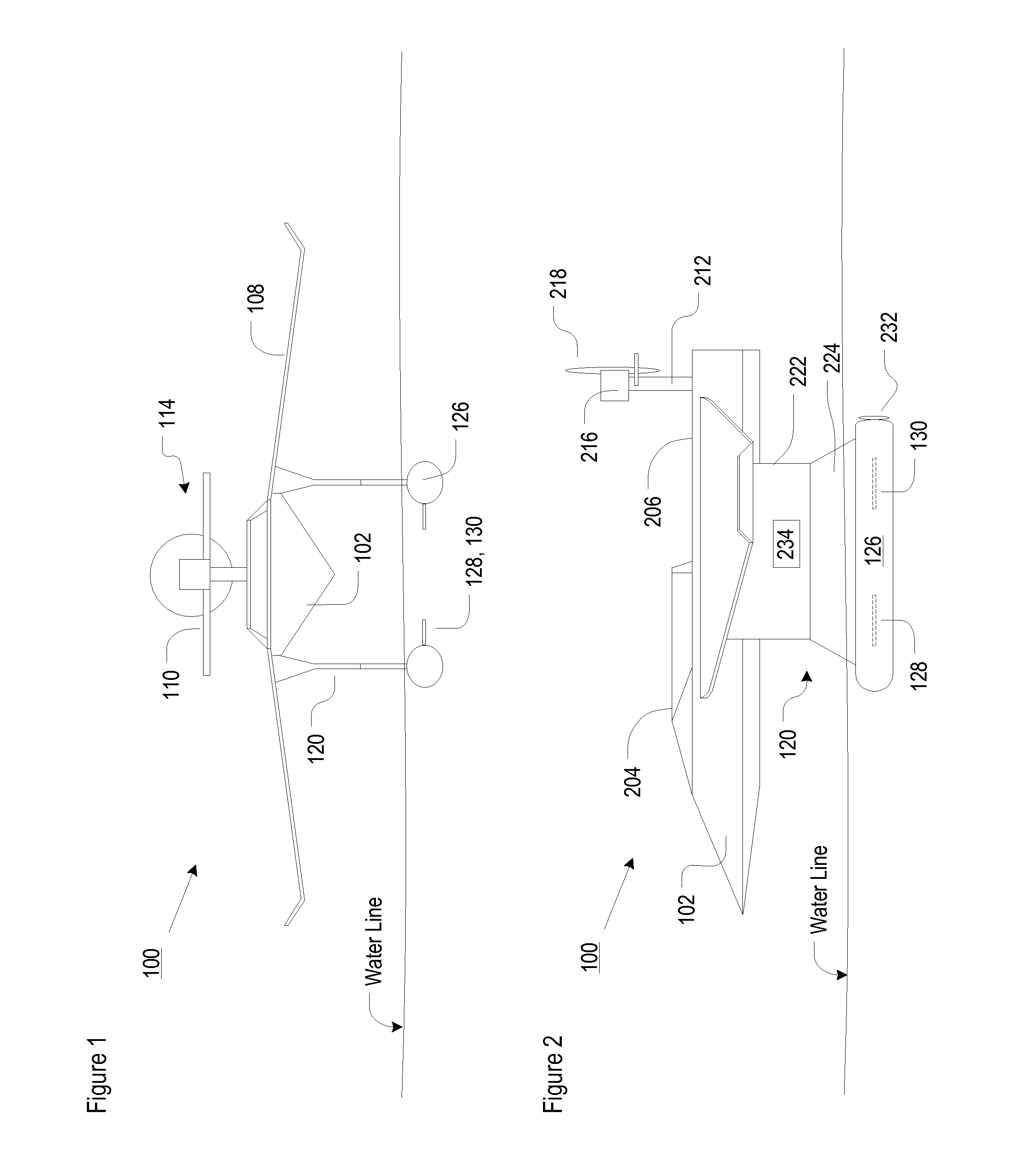
[0015]Those skilled in the art will recognize that the illustrative embodiment possesses some elements of both SWATH craft and WIG craft. In particular, the vessel includes the submerged lower hulls and extended struts characteristic of a SWATH craft. The lower hulls provide “lift” via displacement. Because they are submerged, the lower hulls do not follow surface wave motion. By way of analogy, consider the relatively common experience of “ducking” under a large wave, versus remaining at the water's surface, while swimming in the ocean. The affect on the stability of a person or a vessel is the same. That is, a submerged body is affected far less by wave motion than a body that is afloat at the water's surface. In other words, stability is substantially increased by submerging.
[0016]In the illustrative embodiment, the vessel will remain stable at speed as long as its upper hull does not contact the water. Once it does, the vessel follows wave motion. This is a purpose of the struts; to raise the upper hull above the water line. The larger the distance between the lower hull(s) and the upper hull (i.e., the longer the struts), the higher the sea state in which the vessel can maintain stable operation. Furthermore, the struts have a small waterplane area (i.e., the cross sectional area at the waterline). This results in longer natural periods and reduced buoyancy-force changes. Hull fins (i.e., conards, stabilizers) provide additional motion damping and dynamic stabilization when underway. Collectively, these SWATH-based attributes provide a high degree of stability to a marine vessel in accordance with the illustrative embodiment.
[0017]But the vessel also possesses the wings and the above-the-water-line propulsion unit (e.g., turbine, propellers, etc.) characteristic of a WIG craft. In the illustrative embodiment, the dynamic lift provided by the wings supplements the lift—buoyancy—provided by the lower hulls. This reduces the displacement requirement of the lower hulls. As a consequence, the lower hulls can be made smaller than would otherwise be the case, which reduces drag, thereby increasing speed.
[0019]If, for example, the vessel is to be used in relatively calm waters, the stability benefits of the SWATH sea frame are of reduced importance. As a consequence, the vessel can be designed for relatively higher speeds by de-emphasizing SWATH characteristics in favor of WIG characteristics. In particular, in some embodiments, the vessel is designed so that a relatively greater proportion of the required lift is provided by the wings, etc., and a relatively lesser proportion is provided by the lower hulls. The size of the lower hulls can, therefore, be reduced. This reduces drag and increases speed. As a practical matter, the lower hulls must have a certain minimum size, at least in embodiments in which they are to provide all lift for the vessel when it is stationary. To this end, the vessel contains buoyancy tanks by which the ballast of vessel is adjusted. Thus, in calm water, the tanks can be at least partially flooded, decreasing the ballast that is provided by the lower hulls.
[0020]Conversely, if the vessel is to be used in very high sea states, then the stability benefits of the SWATH sea frame are of increased importance. As a consequence, the vessel can be designed for relatively higher stability by emphasizing SWATH characteristics and deemphasizing WIG characteristics. In particular, in some embodiments, the vessel is designed so that a relatively greater proportion of the required lift is provided by the lower hulls and a relatively lesser proportion is provided by above-the-water-line lift-providing elements (e.g., wings, etc.). The struts can be lengthened to increase the distance between the lower hulls and the upper hull, thereby enabling operation in greater sea states.

Problems solved by technology

But a static-lift craft becomes relatively inefficient when it is required to move through the surrounding medium (water).
Due to the nature of displacement buoyancy, static-lift craft develop a substantial amount of dynamic drag when in motion.
As a result, this type of craft cannot operate, as such, at relatively slower speeds.

Method used


Image

  • Stable, high-speed marine vessel
  • Stable, high-speed marine vessel

Examples


Embodiment Construction

[0023]FIG. 1 depicts a front view and FIG. 2 depicts a side view of marine vessel 100 in accordance with the illustrative embodiment of the present invention. Referring now to both Figures, vessel 100 includes upper hull 102, wings 108, struts 120, and lower hulls 126, interrelated as shown.

[0024]Upper hull 102 includes cockpit or pilot house 204 and deck 206. In some embodiments, deck 206 is enclosed (not depicted) to provide a protected storage area. Upper hull 102 is advantageously configured with stealth surfaces (e.g., angled surfaces, etc.) and materials to reduce its signatures (e.g., radar, infrared, etc.).

[0025]Wings 108 are disposed amidship; they depend from upper hull 102. As described in further detail later in this specification, wings provide lift (i.e., dynamic lift), when vessel is underway at sufficient speed. In the illustrative embodiment, the wings are not designed for flight; they simply supplement the lift (i.e., buoyancy) provided by lower hulls 106.

[0026]Tai...


PUM


Abstract

A marine vessel that possesses a capability for greater speed than most static-lift craft and is more stable than most dynamic-lift craft is disclosed. The vessel incorporates elements from both SWATH craft and WIG craft. In the illustrative embodiment, the marine vessel includes an upper hull that is disposed above the water line, a dynamic-lift-providing element that is disposed above the water line, a propulsion system that is disposed above the water line, a static-lift-providing element that is disposed below the water line, a propulsion system that is disposed below the water line; and struts that couple the static-lift-providing element to the upper hull and that raise the upper hull some distance above the water line.

Description

FIELD OF THE INVENTION[0001]The present invention relates generally to marine vessels, and more particularly to marine vessels that are stable at relatively high speeds.BACKGROUND OF THE INVENTION[0002]Marine vehicles can be categorized as either static-lift (displacement) craft or dynamic-lift craft. Static-lift craft tend to be more stable than dynamic-lift craft, but slower than them.[0003]For a static-lift craft, buoyant force is generated by the displacement of a portion of the supporting medium, which is water for the case of a marine vessel. Dynamic-lift craft derive their lift from the movement of a foil (e.g., wing, etc.) through air, water, or both.[0004]Static lift is more economical than dynamic lift from a production-of-lift point of view. But a static-lift craft becomes relatively inefficient when it is required to move through the surrounding medium (water). Due to the nature of displacement buoyancy, static-lift craft develop a substantial amount of dynamic drag when...

Claims


Application Information

Patent Timeline
Patent Type & Authority Patents(United States)
IPC IPC(8): B63B1/16B63B1/00
CPCB63B1/322Y02T70/12Y02T70/10
Inventor WATTS, MICHAEL A.
Owner LOCKHEED MARTIN CORP
Learn More