Liquid ejection apparatus and liquid ejection head
a liquid ejection apparatus and liquid ejection technology, applied in printing and other directions, can solve the problems of deteriorating image quality, fluctuation of dynamic pressure, color unevenness in formed images, etc., and achieve the effect of stably ejecting
- Summary
- Abstract
- Description
- Claims
- Application Information
AI Technical Summary
Benefits of technology
Problems solved by technology
Method used
Image
Examples
first embodiment
(First Embodiment)
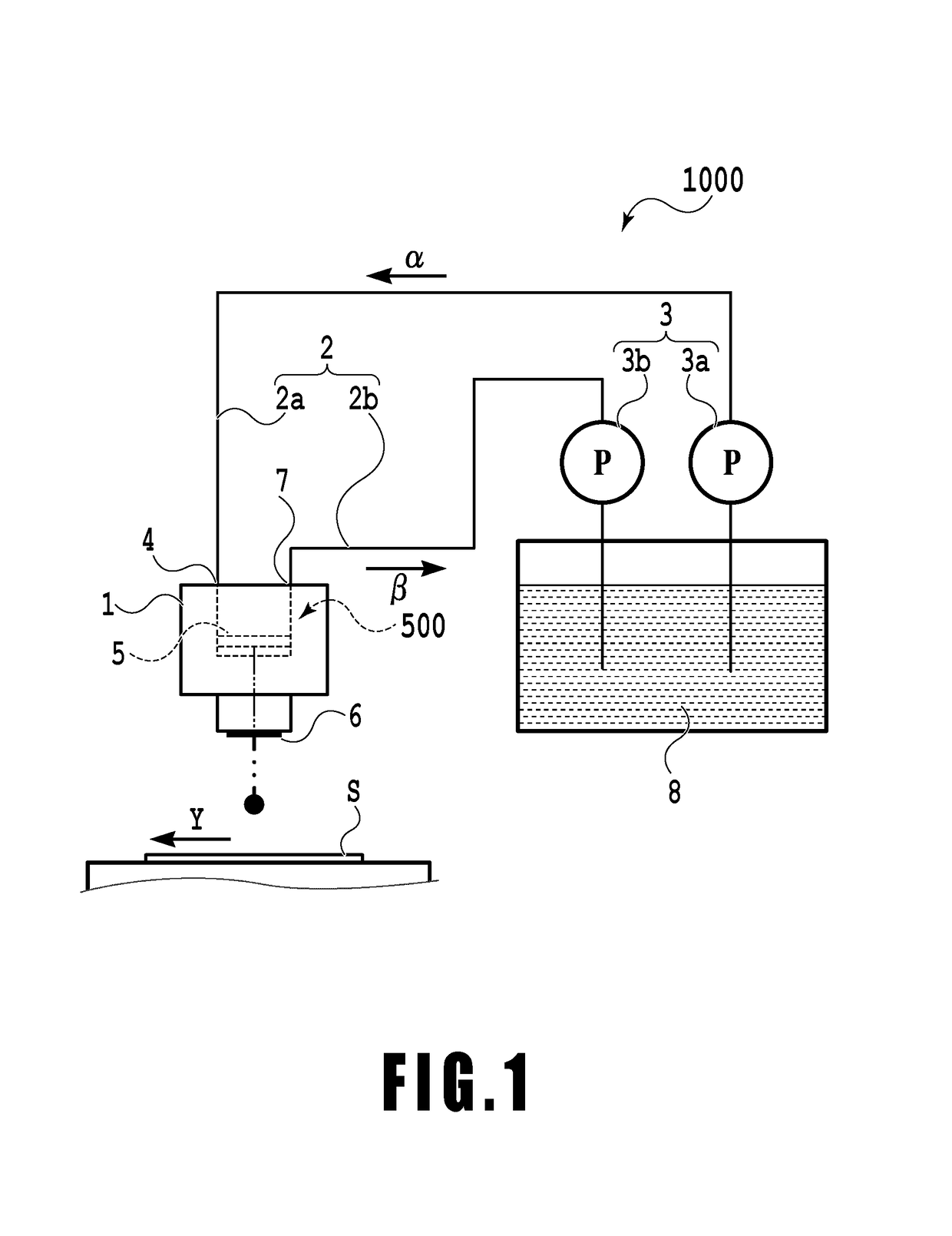
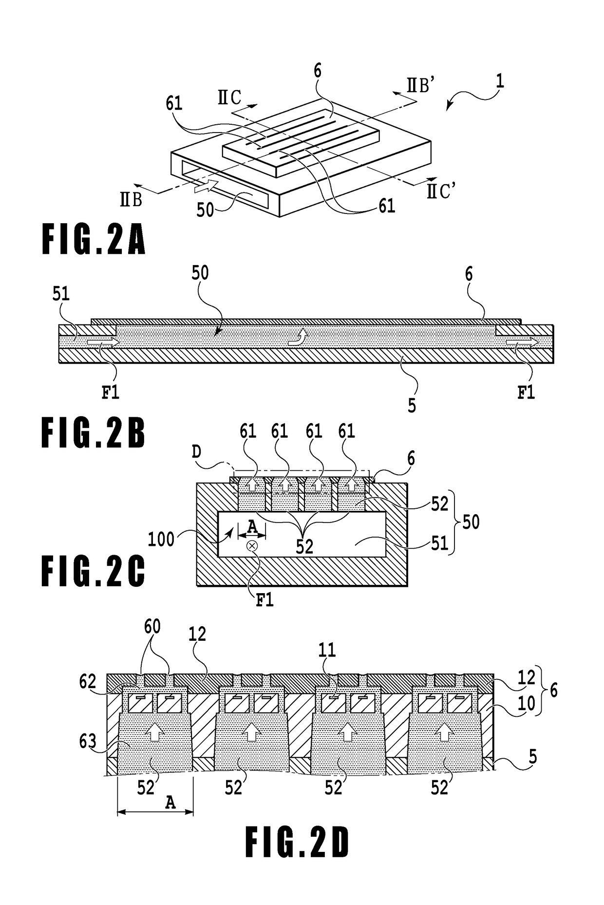
[0028]FIGS. 1 to 7 are diagrams depicting a first embodiment of a liquid ejection apparatus according to the present invention. In the present embodiment, as the liquid ejection apparatus, an ink jet printing apparatus (hereinafter simply referred to as a printing apparatus) that ejects ink onto a print medium to form an image thereon will be described by way of example. The ink as used herein includes not only a liquid containing a coloring material used to form an image on a print medium but also a treatment liquid intended to improve fixability and weatherability of the image formed on the print medium.
[0029]FIG. 1 is a schematic diagram depicting a basic configuration of a printing apparatus 1000 in the present embodiment. The printing apparatus 1000 includes a liquid ejection head 1 and a liquid storage 8 that stores ink to be fed to the liquid ejection head 1. The printing apparatus 1000 further includes an extra-head flow path 2 that couples the liquid stora...
second embodiment
(Second Embodiment)
[0076]Now, a second embodiment of the present invention will be described with reference to FIGS. 9A to 9C. FIGS. 9A to 9C are schematic diagrams depicting the printing element 11 and components around the ejection port. FIG. 9A illustrates a state before ink ejection, FIG. 9B illustrates a state during ink ejection, and FIG. 9C illustrates a state after ink ejection.
[0077]The present embodiment has an efficient configuration in which 70% or more, that is, substantially all of ink (liquid) 13 on an energy generating element in the pressure chamber changes to an ink droplet (droplet) 14a, which is then ejected. To allow an ink droplet to be ejected in a larger ejection volume from such a liquid ejection head, the diameter of each ejection port needs to be further increased. However, an increased diameter of the ejection port causes the meniscus in the ejection port to be more significantly displaced in response to a fluctuation in pressure. As a result, the ejectio...
third embodiment
(Third Embodiment)
[0079]Now, a third embodiment of the present invention will be described.
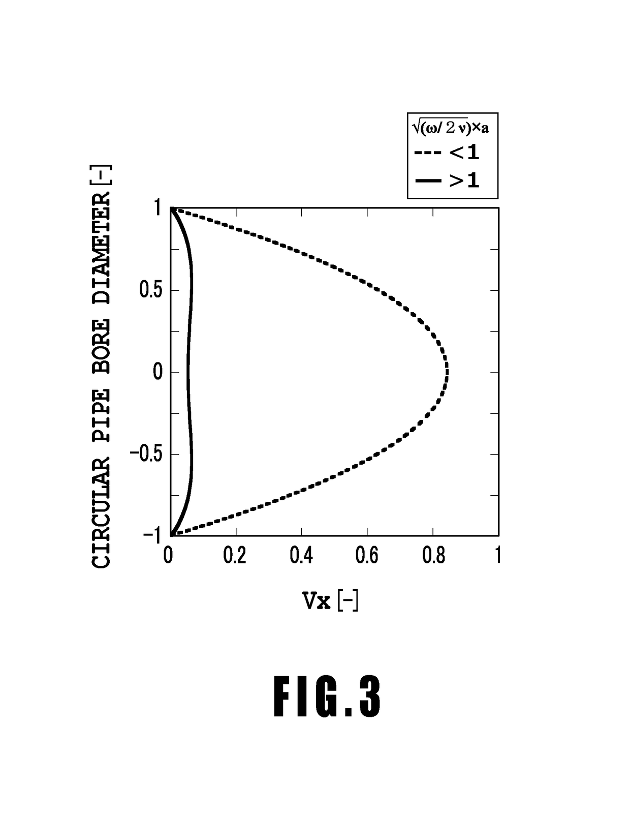
[0080]In the first embodiment, an example has been illustrated where the indicator for the intra-head flow path 100 is equal to or smaller than 1 (√(ω / 2ν)×a≤1) and where the radially enlarged component serving to set the indicator larger than 1 is formed at least in a part of the extra-head flow path 2. In contrast, in the third embodiment, the indicator for the intra-head flow path 100 formed in the liquid ejection head is designed to be larger than 1.
[0081]FIGS. 10A to 10D are diagrams depicting a configuration of a liquid ejection head 200 in the third embodiment. FIG. 10A is a perspective view. FIG. 10B is a sectional view taken along line XB-XB′ in FIG. 10A, and FIG. 10C is a sectional view taken along line XC-XC′ in FIG. 10A. Components in FIGS. 10A to 10D that are the same as or correspond to particular components of the liquid ejection head 1 depicted in FIGS. 2A and 2B are denoted by ...
PUM
 Abstract
Description
Claims
Application Information
 - R&D
- Intellectual Property
- Life Sciences
- Materials
- Tech Scout
- Unparalleled Data Quality
- Higher Quality Content
- 60% Fewer Hallucinations
Browse by: Latest US Patents, China's latest patents, Technical Efficacy Thesaurus, Application Domain, Technology Topic, Popular Technical Reports.
© 2025 PatSnap. All rights reserved.Legal|Privacy policy|Modern Slavery Act Transparency Statement|Sitemap|About US| Contact US: help@patsnap.com


