
Device for measuring the geometry of a wheel axle of a motor vehicle

a technology for measuring the geometry of the wheel axle and the motor vehicle, which is applied in the direction of angles/taper measurements, instruments, transportation and packaging, etc., can solve the problem of insufficient space and achieve the effect of reducing the manufacturing cost of the wheel hub dome and simple manner

Active Publication Date: 2019-03-19
A U E KASSEL
View PDF24 Cites 1 Cited by
  • Summary
  • Abstract
  • Description
  • Claims
  • Application Information

AI Technical Summary

Benefits of technology

[0010]This has the advantage that by it the wheel hub is held in close fit and thus in a defined position in the wheel hub dome so that a precise measurement, for example, on the brake disk of the wheel axle can occur.
[0011]In a particularly preferred embodiment in an area of the wheel hub dome facing the wheel hub an introduction step for grasping the wheel hub and / or for introduction of the wheel hub into the wheel hub dome is provided, which is configured in an inclined manner by an angle of 45° relative to the longitudinal axis of the wheel axle. In another embodiment the angle can be between 30° and 60°. Via said introduction phase configured similar to a conical recess, the entry area of the wheel hub dome is enlarged with the advantage that when approaching the wheel axle onto the wheel hub support, the entry area of the wheel hub dome enlarged by the introduction phase will find the wheel hub even if the wheel axle is not exactly aligned to the wheel hub support. After the wheel hub dome has found the wheel hub, the latter is grasped by the introduction phase and lead into the wheel hub dome until the outer side of the wheel hub abuts the bearing surface. This has the advantage that by this the wheel axle can be rapidly and reliably lead into the guided position within the wheel hub dome, whereby the cycle times during measurement of the geometry of the wheel axle can be kept at a low level. Moreover, such a wheel hub dome has very low manufacturing cost.
[0014]In another preferred embodiment a number of segment teeth are formed inside the wheel hub dome. The size, the shape and the number of segment teeth corresponds here with the wheel hub so that the segment teeth transmit the rotational movement of the device by a positive connection onto the segmented wheel hub. This has the advantage that the wheel hub rotates synchronously and without any slip with the device, for example, in order to carry out a measurement of axial run-out.
[0015]In a preferred further embodiment the segment teeth are formed in one piece to the wheel hub dome. This has the advantage that an assembly of the device can occur in a simple manner and that the manufacturing cost of the wheel hub dome are reduced.
[0016]In an another particularly preferred embodiment on the device for measuring the geometry of the wheel axle of a motor vehicle apart from the wheel hub support and in parallel to the longitudinal axis a drive pin is provided, which in its rest position is provided within the device, but which is axially displaceable from said rest position up and into an opening of the wheel axle. This has the advantage that the wheel axle is entrained via the drive pin as soon as the device for measuring the geometry is set in rotation. In this manner the wheel axle becomes slip-free and is set in rotation with the same speed as the device, for example, in order to carry out a measurement of axial run out.
[0017]In a preferred further embodiment the drive pin is preloaded with a spring. This has the advantage that the spring keeps the drive pin reliably engaged with the wheel axle in order to prevent an unintentional sliding out of the drive pin.

Problems solved by technology

In the case of some wheel axles, there is not enough space in order to form a sufficiently large bearing surface and a sufficiently large introduction phase on the wheel hub dome.

Method used


Image

  • Device for measuring the geometry of a wheel axle of a motor vehicle
  • Device for measuring the geometry of a wheel axle of a motor vehicle
  • Device for measuring the geometry of a wheel axle of a motor vehicle

Examples


first embodiment

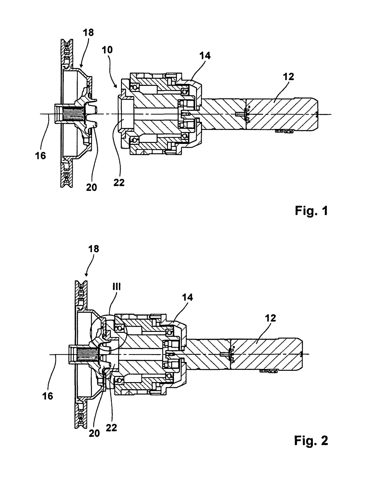
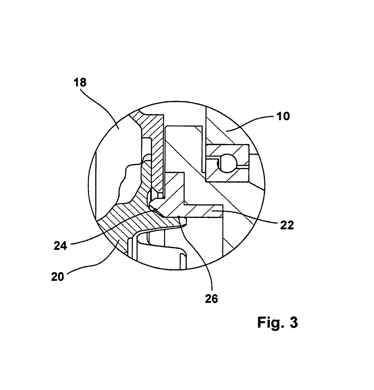
[0037]The first embodiment shown in FIGS. 1 to 3 comprises moreover means not shown here in detail for the creation of a pressing force 14 acting axially onto the wheel hub dome 22 by means of which the wheel hub dome 22 is pressed against the wheel axle 18 in order to lead the wheel hub 20 reliably deep into the wheel hub dome 22, and, if required, hold it in said position during the measuring operation.

[0038]The wheel hub 20 shown in said first embodiment is formed as a segmented wheel hub. As can be seen in FIGS. 1 to 3, said segmented wheel hub 20 can also be taken up by the wheel hub dome 22 without any difficulties, and be held in said wheel hub dome in a precisely defined manner. But in another embodiment the wheel hub can be formed in a closed manner, as is shown in FIG. 4.

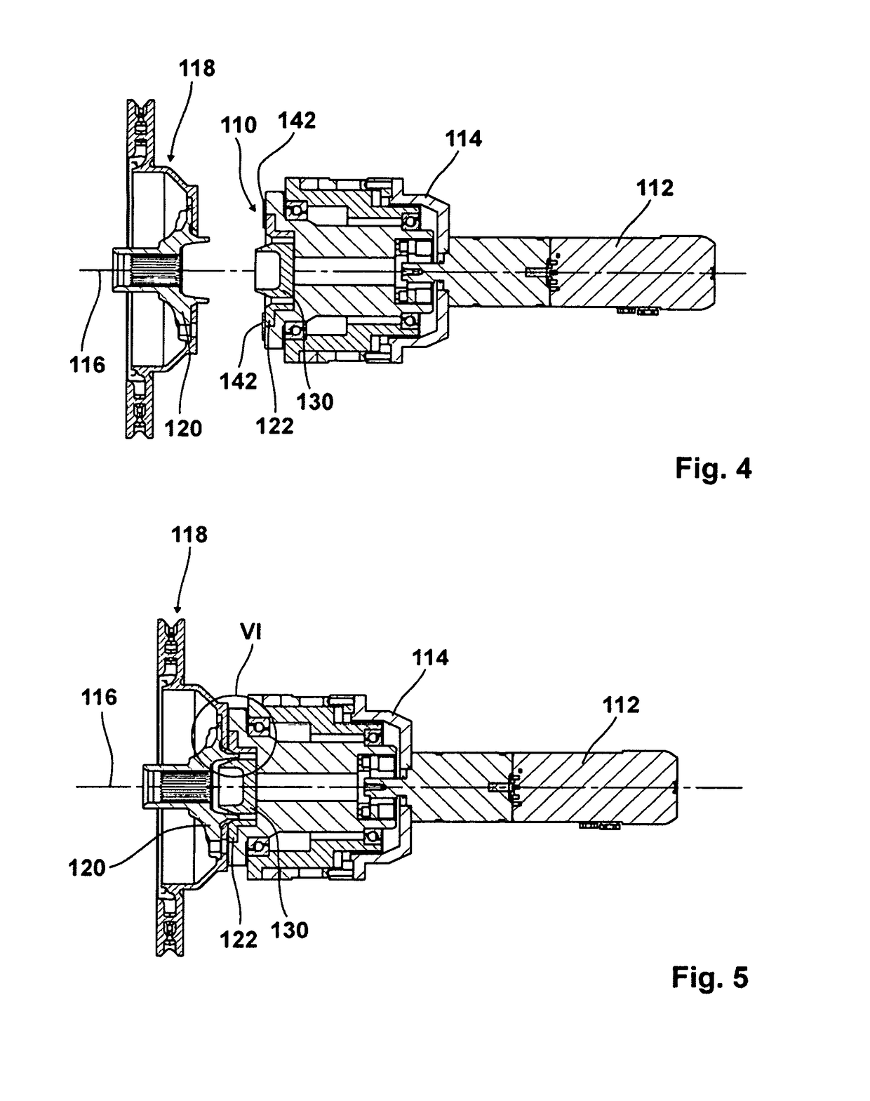
[0039]In FIGS. 4 to 6 a second embodiment of a device according to the invention for measuring the geometry of a wheel axle of a motor vehicle is shown which shall measure a second embodiment of a wheel ax...

second embodiment

[0042]Also, in the second embodiment shown here means for pressing 114 the wheel hub dome 122 against the wheel hub 120 are provided in order to lead the wheel hub 120 reliably deep into the wheel hub dome 122, and hold in said position during the measuring operation, if required. In said end position the wheel hub support 110 with its spacers 142 abuts the wheel axle 118.

[0043]The wheel hub mandrel 130 is arranged coaxially to the wheel hub dome 120 and possesses on its outer side a lead-in chamfer 132 via which the wheel hub 120 is lead into the desired position. The lead-in chamfer 132 of the wheel hub mandrel 130 cooperate with the shortened introduction phase 124 of the wheel hub dome 122 here in order that the wheel hub 120 is grasped reliably and lead into the desired position within the wheel hub dome 122 while the device is approached to the wheel axle 118 in the direction of the longitudinal axis 116.

[0044]In the embodiment shown here the lead-in chamfer 132 is inclined by...


PUM


Abstract

A device for measuring the geometry of a wheel axle of a motor vehicle comprising a wheel hub support for defined positioning of a wheel hub of the wheel axle. The wheel hub support comprises a wheel hub dome formed correspondingly to an outer side of the wheel hub and encompassing the wheel hub dome in a precise fit.

Description

CROSS-REFERENCE TO RELATED APPLICATION[0001]This application claims priority to German Patent Application No. 10 2015 010 803.4 filed on Aug. 21, 2015, the contents of which are incorporated herein by reference.BACKGROUND OF THE INVENTION1. Field of the Invention[0002]The present invention relates generally to the field of devices used in the manufacture of motor vehicles, and more particularly, to a device for measuring the geometry of a wheel axle of a motor vehicle in an assembly line.2. Description of the Related Art[0003]From DE 11 2004 000 871 B4 a device for measuring the geometry of a wheel axle of a motor vehicle is known where the wheel flange pickup is formed as a chuck with three radially movable clamping jaws, with the clamping jaws by radially grasping the hub and corresponding fixation of the hub hold the wheel axle onto the device. By said fixed position, the hub and thus also the wheel axle of the motor vehicle can be set in rotation in order to carry out measuring ...

Claims


Application Information

Patent Timeline
Patent Type & Authority Patents(United States)
IPC IPC(8): G01B5/25B62D65/00B60B35/00B60B27/00G01B5/255
CPCG01B5/255B60B27/00G01B5/25B62D65/005B60B35/00G01B5/0025G01B2210/12
Inventor NOURDINE, AHMED
Owner A U E KASSEL
Learn More