Shift range controller

a range controller and shift range technology, applied in the direction of electric controllers, electronic commutators, gearing elements, etc., can solve the problems of invalidating the correction of the motor angle target value based on such output shaft signals, and affecting the control of the motor

Active Publication Date: 2019-03-19
DENSO CORP
View PDF2 Cites 0 Cited by
  • Summary
  • Abstract
  • Description
  • Claims
  • Application Information

AI Technical Summary

Benefits of technology

[0006]It is an object of the present disclosure to provide a shift range controller that improves the setting of a motor angle target value based on a requested shift range.
[0015]In such manner, erroneous correction of the motor angle target value affected by noise and / or chatter is limited or prevented.

Problems solved by technology

In instances where the switch is used as the output shaft sensor for setting a target position of the motor based on the output of the switch, motor control may be affected due to an abrasive powder or an electrical noise that hinders a detection of the sensor signal edges.
Further, when the number of edges detected in the detection range is greater than the legitimate number, or when the edge is detected outside the detection range, the target angle setter invalidates a correction of the motor angle target value based on the relevant output shaft signal.
Further, when the number of edges detected in the detection range is greater than the legitimate or normal number of edges, or when the edge is detected outside of the detection range, the output shaft signal corresponding to such detected edge(s) may include signal noise and / or signal chatter, and the correction of the motor angle target value based on such output shaft signal is invalidated.

Method used


Image

  • Shift range controller
  • Shift range controller
  • Shift range controller

Examples


Embodiment Construction

[0030]Hereafter, the shift range controller of the present disclosure is described based on the drawings.

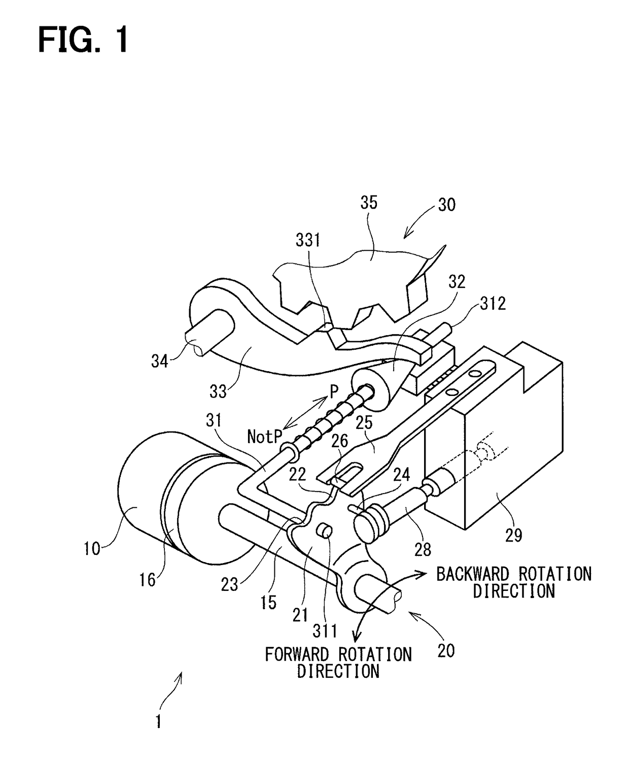
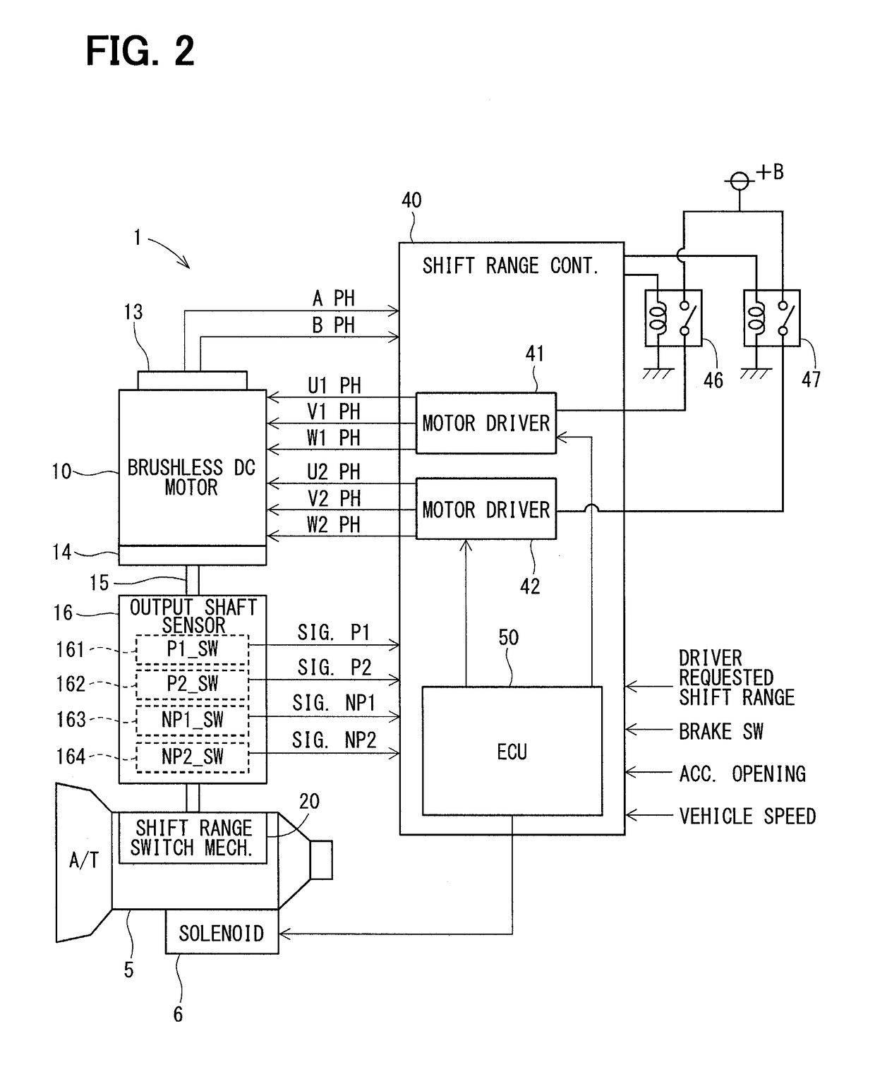
[0031]As shown in FIGS. 1 and 2, a shift-by-wire system 1 may include a motor 10, a shift range switch mechanism 20, a parking lock mechanism 30, a shift range controller 40, and the like.

[0032]Electric power supplied from a battery 45 (FIG. 4) is used to rotate motor 10 to provide drive power to the shift range switch mechanism 20. Using feedback control, the motor 10 may receive a variable magnitude of electric current, and control instructions for the motor 10 may also change for each of the various phases. The motor 10 of the present embodiment may be a permanent magnet-type DC brushless motor. As shown in FIG. 4, the motor 10 has 2 sets of winding groups, a first winding group 11 and a second winding group 12. The first winding group 11 has a U1 coil 111, a V1 coil 112, and a W1 coil 113. The second winding group 12 has a U2 coil 121, a V2 coil 122, and a W2 coil 123.

[0033]A...


PUM


Abstract

A shift range controller includes a target angle setter obtaining, from an output shaft sensor, sensor signals provided by switches. The target angle setter corrects a target count value that corresponds to a requested shift range, based on the respective sensor signals. When a legitimate number of edges are detected within a signal detection range, or an edge detection window for detecting at least one of the sensor signals (e.g., P1 signal), the target angle setter calculates a post-correction target count value based on an actual count value at an edge detection timing. When the number of edges detected in the detection window is greater than the legitimate number, or, when the edge is detected at a position outside the detection window for at least one of the sensor signals, the target angle setter invalidates the correction of the target count value based at least on the one of the sensor signals.

Description

CROSS REFERENCE TO RELATED APPLICATION[0001]The present application is based on and claims the benefit of priority of Japanese Patent Application No. 2016-209324, filed on Oct. 26, 2016, the disclosure of which is incorporated herein by reference.TECHNICAL FIELD[0002]The present disclosure generally relates to a shift range controller.BACKGROUND INFORMATION[0003]Conventionally, a shift range switch device controls the switching between a plurality of shift ranges in response to a driver's request for switching the shift ranges. For example, a system / controller described in patent document 1 below includes an output shaft sensor that detects a rotation angle of an output shaft engaged with a rotation shaft of a speed reduction mechanism for reducing a rotation speed of a motor.[0004](Patent document 1) Japanese Patent No. 4385768[0005]The patent document 1 shows, as an example of the output shaft sensor, (i) a potentiometer that generates a linearly changing output voltage based on t...

Claims


Application Information

Patent Timeline
Patent Type & Authority Patents(United States)
IPC IPC(8): G05B11/01H02P6/16H02P6/08
CPCH02P6/08H02P6/16F16H61/32F16H2061/326
Inventor KAMIO, SHIGERU
Owner DENSO CORP
Why Eureka
Try Eureka