Apparatus for and method of optimizing the performance of a radio frequency receiver in the presence of interference

a radio frequency receiver and interference signal technology, applied in the field of communication receiver circuits, can solve the problems of increased frequency generation, increased noise figure (nf), and undesired intermodulation products

Inactive Publication Date: 2005-11-15
TEXAS INSTR INC
View PDF8 Cites 65 Cited by
  • Summary
  • Abstract
  • Description
  • Claims
  • Application Information

AI Technical Summary

Benefits of technology

[0029]By adapting the mixer to have two gain states, the flexibility of the RF receiver is greatly improved with respect to the tradeoff between sensitivity and linearity described above in the Background section. For example, when the mixer is set to the low gain mode of operation while the LNA is set to the high gain mode of operation, the sensitivity of the RF receiver is greatly improved without sacrificing receiver linearity as compared to the response of the receiver when the gain of the LNA is set low and the gain of the mixer is set high. Since the major affect on the linearity of the receiver is the linearity of the mixer, setting the mixer to a low gain state improves the linearity of the receiver to a greater extent that when the LNA is set to low gain mode and the mixer to high gain mode.

Problems solved by technology

The nonlinearities of these components cause the generation of the additional frequencies.
In addition, undesired intermodulation products are also produced.
In silicon integrated circuit (IC) design, however, a higher intercept point typically results in a higher Noise Figure (NF).
Such a wide input band permits not just the desired signal to enter the receiver but a large amount of undesired signals as well.
These goals, however, conflict with one another.
In this case, large levels of noise and undesirable signals enter the mixer and discriminator due to the requirement of receiving all the channels in the band.
As in receivers based on discrete components, and in RF integrated circuit design, a higher 3rd order intercept point results in a high NF that could potentially degrade the performance of the receiver when weak signals are received.
Therefore, in many cases the linearity of the receiver is limited by the 3rd order intercept point of the first mixer that must handle an amplified signal.
Setting the gain of the LNA to high gain mode places a considerable limitation on the linearity of the receiver.
The limitation on linearity of the receiver is due to the low 3rd order intercept point of the first mixer stage.
The reduction of LNA gain by 10 to 15 dB, intended to reduce the susceptibility of the receiver front end to nonlinear effects, causes an increase in the noise figure of the receiver and reduces its sensitivity.
In some cases, it is not appropriate to switch the LNA to low gain mode.
For example, in the case of near band high interference, the performance level of the receiver may fall below acceptable levels since the desired signal may be too low and the near band interference signal too high.
Further, in some cases, switching the LNA to a low gain mode of operation does not result in a significant enough improvement of the linearity of the receiver.

Method used


Image

  • Apparatus for and method of optimizing the performance of a radio frequency receiver in the presence of interference
  • Apparatus for and method of optimizing the performance of a radio frequency receiver in the presence of interference
  • Apparatus for and method of optimizing the performance of a radio frequency receiver in the presence of interference

Examples


Embodiment Construction

Notation Used Throughout

[0046]The following notation is used throughout this document.

[0047]

TermDefinitionBERBit Error RateBPFBand Pass FilterCMOSComplementary Metal Oxide SemiconductorFETField Effect TransistorFMFrequency ModulationFSKFrequency Shift KeyingHEMTHigh Electron Mobility TransistorICIntegrated CircuitIFIntermediate FrequencyIP33rd Order Intercept PointISMIndustrial Scientific MedialLNALow Noise AmplifierLOLocal OscillatorMESFETMetal Semiconductor Field Effect TransistorNFNoise FigureNMOSN-Type Metal Oxide SemiconductorPHEMTPseudomorphic Hetero Junction Field Effect TransistorPLLPhase Lock LoopRFRadio FrequencyRSSIReceived Signal Strength IndicationSCOSynchronous Connection Oriented linkVCOVoltage Controlled Oscillator

DESCRIPTION OF THE INVENTION

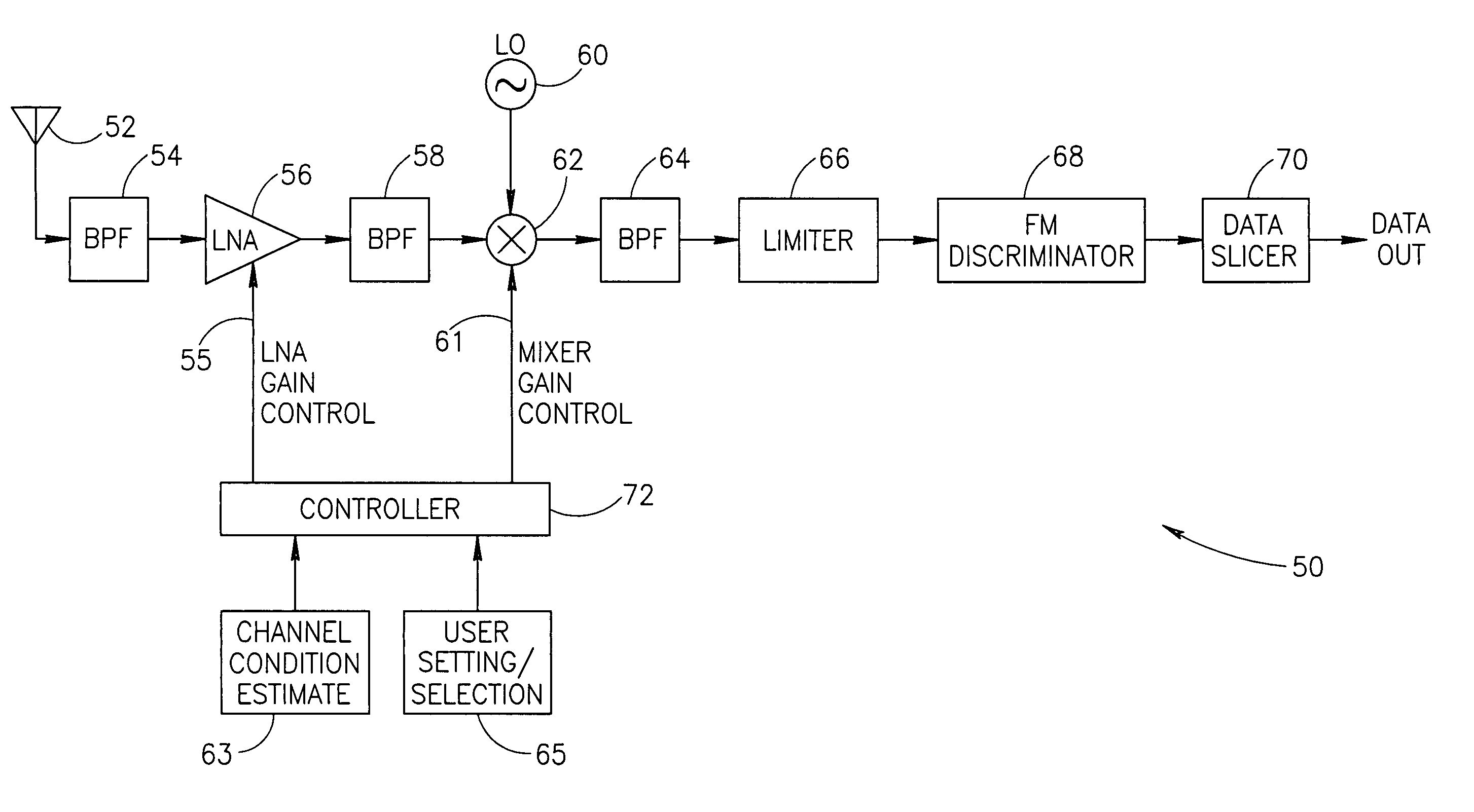
[0048]The present invention comprises an apparatus for and method of extending the dynamic range of a RF communications receiver. The invention functions to provide a control mechanism for controlling the gain of both the LNA and...


PUM


Abstract

An apparatus for and method of extending the dynamic range of a RF communications receiver. The invention provides a mechanism for controlling the gain of both the LNA and down conversion mixer in the front end portion of an RF receiver. Both the LNA and the mixer are adapted to have both low and high gain modes of operation. The control mechanism typically comprises a two bit gain control that places both the LNA and mixer in one of four operating gain mode states. The selection of the most appropriate operating gain mode state, is preferably determined in accordance with various metrics such as the received levels of the desired signal, levels of interference signals, bit error rate and receiver RSSI.

Description

FIELD OF THE INVENTION[0001]The present invention relates generally to communications receiver circuits and more particularly relates to an apparatus for and method of optimizing the Radio Frequency (RF) receiver performance in the presence of interfering signals.BACKGROUND OF THE INVENTION[0002]High frequency radio frequency (RF) communications are becoming more and more prevalent in the world today. Products touting wireless RF communication links are becoming increasingly popular among consumers. A multitude of new products including redesigned existing ones is being built with wireless RF links today. A RF link is based on a transmitter that emits a RF signal representing the information sent, and a communication receiver that receives the transmitted signal and extracts the information transmitted therefrom. To do this, modern RF receivers use an assortment of components such as amplifiers, filters, mixers, detectors, VCOs, PLLs, etc. A common goal in designing a receiver is to...

Claims


Application Information

Patent Timeline
Patent Type & Authority Patents(United States)
IPC IPC(8): H04L27/02H04L27/08H03G3/30H03G11/00H04B1/10H04B1/18
CPCH03G3/3068H03G11/00H04B1/1027H04B1/18
Inventor MOSTOV, ALEXANDERELIEZER, OREN
Owner TEXAS INSTR INC
Why Eureka
Try Eureka