Film transfer tool

a technology of film transfer and tool, which is applied in the field of film transfer tools, can solve the problems of increasing the tension of the transfer tape, affecting the transfer operation, and affecting the smoothness of the transfer operation,

Active Publication Date: 2019-03-26
PLUS CORP
View PDF10 Cites 0 Cited by
  • Summary
  • Abstract
  • Description
  • Claims
  • Application Information

AI Technical Summary

Benefits of technology

[0008]An object of the invention is to provide a film transfer tool which can be restored to a normal use state even in the event that a small degree of sticking of a transfer tape takes place.
[0016]In this way, when the small degree of sticking of the transfer tape takes place, by transmitting the rotational force to the second rotational connection mechanism, the take-up bobbin can be rotated to take up the transfer tape, or the supply bobbin and the take-up bobbin are caused to stop rotating so that the user can be made to sense that the transfer tape is sticking. Therefore, the sticking state of the transfer tape can easily be eliminated to restore the normal transfer operation.
[0017]In addition, by providing the second clutch on the second rotational connection mechanism, even in case a small degree of sticking of the transfer tape takes place whereby the rotational force is transmitted to the second rotational connection mechanism, the difference in rotation speed between the supply bobbin and the take-up bobbin can be adjusted by the second clutch. Consequently, even in case a small degree of sticking of the transfer tape takes place in the normal transfer operation, the take-up bobbin is rotated by continuing to perform the transfer operation, whereby the small degree of sticking of the transfer tape can be eliminated so as to restore the normal transfer operation.
[0018]Additionally, in the event that the clutch force of the second clutch is smaller than the clutch force of the first clutch, even in case the transfer mode is switched from the normal transfer operation to the transfer operation for the small degree of sticking due to the small degree of sticking taking place, a change in operation effort to operate the film transfer tool can be reduced. Consequently, the user of the film transfer tool can continue to use the film transfer tool without feeling the sensation of physical disorder.
[0020]The ratchet shaft is concentric with the supply-side rotational shaft and includes the ratchet teeth that are formed on the outer circumference thereof. Then, the ratchet rotational member constitutes a locking claw that is brought into locking engagement with the ratchet teeth. By doing so, the film transfer tool can be fabricated more compact.

Problems solved by technology

However, it is difficult for the transfer tape to move also when a small degree of sticking takes place due to an accumulation of dust such as waste of a rubber eraser picked up by the transfer tape on the transfer receiving surface or part of the transfer layer of the transfer tape clogging up a portion in the case where the transfer tape passes, which increases the tension in the transfer tape.
Then, the transfer operation becomes heavy.
However, in the film transfer tool disclosed in Patent Literature 1, the small degree of sticking described above cannot be eliminated.

Method used


Image

  • Film transfer tool
  • Film transfer tool
  • Film transfer tool

Examples


Embodiment Construction

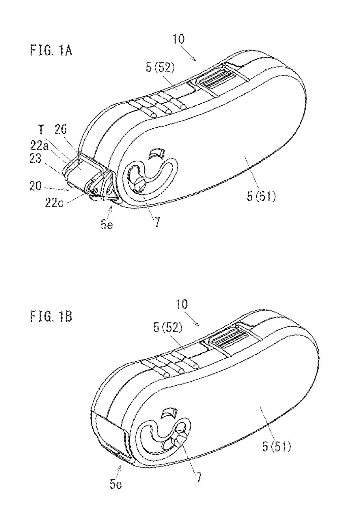
[0030]Hereinafter, an embodiment of the invention will be described based on the drawings. FIG. 1A is perspective views of an in-use state of a film transfer tool 10. FIG. 1B is perspective views of a retracted state of a film transfer tool 10. The film transfer tool 10 includes a case main body 5. The film transfer tool 10 includes a transfer head 20 that transfers a transfer layer of a transfer tape T on to a transfer receiving surface. This transfer head 20 is provided so as to project from and retract into the case main body 5. In the following description, an end portion of the film transfer tool 10 where the transfer head 20 is provided will be referred to as a front thereof, and an opposite end portion of the film transfer tool 10 will be referred to as a rear thereof. When the film transfer tool 10 is seen from the rear to the front, a left side of the film transfer tool 10 will be referred to as a left thereof, and a right side of the film transfer tool 10 will be referred ...


PUM


Abstract

A film transfer tool that can be restored to a normal use state easily even though a small degree of sticking takes place in a transfer tape includes a supply bobbin, a take-up bobbin, a supply-side rotational shaft that is fixed to the supply bobbin, a take-up side rotational shaft that is fixed to the take-up bobbin, a ratchet shaft that is connected rotationally to the supply-side rotational shaft, a first rotational connection mechanism that connects the supply-side rotational shaft and the take-up side rotational shaft together rotationally and which includes a first clutch and a second rotational connection mechanism that connects the ratchet shaft and the take-up side rotational shaft together rotationally via a locking claw that is a ratchet rotational member. A ratio of a rotation speed of the ratchet rotational member to a rotation speed of the ratchet shaft is set to be greater than one.

Description

CROSS-REFERENCE TO RELATED APPLICATION[0001]This application is based upon and claims the benefit of priority under 35 USC 119 from Japanese Patent Application No. 2015-097082 filed on May 12, 2015, the entire disclosure of which, including the description, claims, drawings and abstract, is incorporated herein by reference.BACKGROUND OF THE INVENTION[0002]Field of the Invention[0003]The present invention relates to a film transfer tool that transfers a transfer layer of a transfer tape on to a transfer receiving surface.[0004]Description of the Related Art[0005]Film transfer tools have conventionally been provided for application to transferring a correction tape or a glue tape. For example, Japanese Unexamined Patent Application No. 2009-285883 discloses a film transfer tool in which even though an amount of the used tape that has been taken up by a take-up bobbin is increased to thereby increase the tension in a transfer tape, the tension is lessened.[0006]This film transfer tool ...

Claims


Application Information

Patent Timeline
Patent Type & Authority Patents(United States)
IPC IPC(8): F16D7/02B43L19/00B65H35/00
CPCF16D7/021B65H35/0033B43L19/00B65H2403/731B65H16/10B65H18/08B65H37/007B65H2403/42B65H2403/47B65H2403/72B65H2701/37
Inventor KOBASHI, YOSHIHIKO
Owner PLUS CORP
Why Eureka
Try Eureka