Method and apparatus for pressurized product production

a technology of pressurized products and methods, applied in the direction of indirect heat exchangers, lighting and heating apparatus, stationary plate conduit assemblies, etc., can solve the problems that the cost of such heat exchangers is a major cost of the cryogenic rectification plant, and achieves less heat transfer duty, substantial savings in acquisition costs, and efficient

Active Publication Date: 2010-12-16
PRAXAIR TECH INC
View PDF7 Cites 8 Cited by
  • Summary
  • Abstract
  • Description
  • Claims
  • Application Information

AI Technical Summary

Benefits of technology

[0009]It is to be noted although the claims are addressed to a method of producing a pressurized product stream, it is not intended that the present invention be limited to a cryogenic rectification process or plant employing such process in which only a single pressurized product stream is produced in that the method could be applied to produce a nitrogen-rich product stream or an oxygen-rich product stream or both simultaneously. Further, the term, “main heat exchanger” as used herein and in the claims includes one of such units or several of such units connected in parallel. A principle under which the present invention operates is that it takes more heat to warm the pumped liquid oxygen stream to its critical temperature, if a supercritical fluid is the intended or to the dew point temperature if a vapor product is desired then to afterwards warm either of such streams to the warm end temperature of the main heat exchanger. In the prior art, however, the layers within the main heat exchanger that are used for warming the pumped liquid oxygen stream are designed to warm subsidiary streams thereof from entering the cold end temperature of the pumped liquid oxygen stream to the warm end temperature of the main heat exchanger. Consequently, not all of the heat transfer area provided by the layers in such a prior art heat exchanger are being efficiently used because there is less heat transfer duty in warming the subsidiary streams from the critical temperature or dew point temperature to ambient. In the present invention, however, once the critical temperature or dew point temperature is exceeded, the subsidiary streams are combined leaving regions within the layers available for heating or cooling another stream. In such manner, the main heat exchanger can be fabricated in a more compact manner than in the prior art, resulting in substantial savings in the acquisition costs of such heat exchanger. Moreover, as will be discussed, there are other advantageous operations that are made available by such arrangement in connection with the production of liquid products.

Problems solved by technology

In any event, the cost of such heat exchangers represents a major cost of the cryogenic rectification plant and typically, the price of a particular heat exchanger is based upon its volume.

Method used


Image

  • Method and apparatus for pressurized product production
  • Method and apparatus for pressurized product production
  • Method and apparatus for pressurized product production

Examples


Embodiment Construction

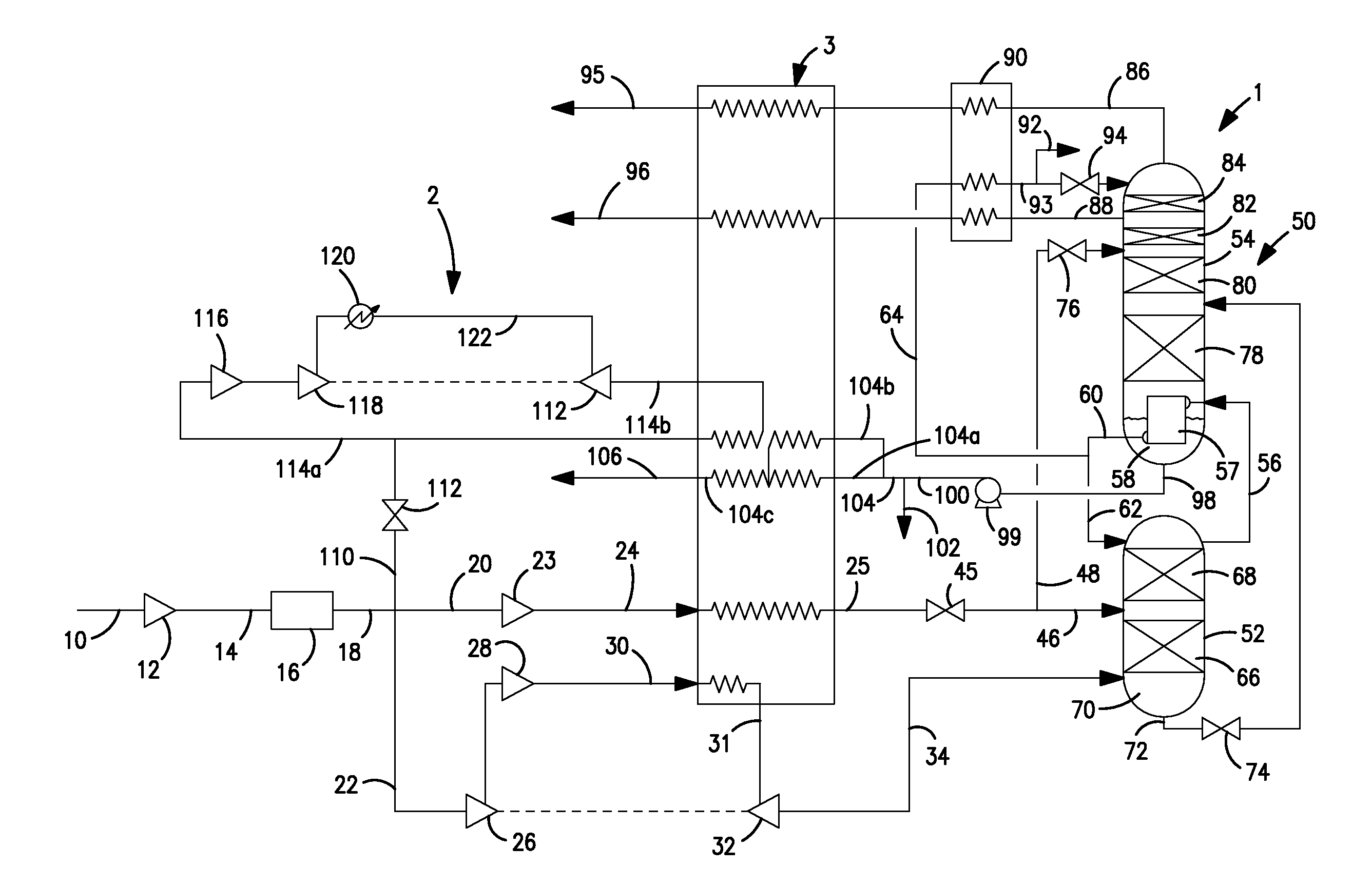
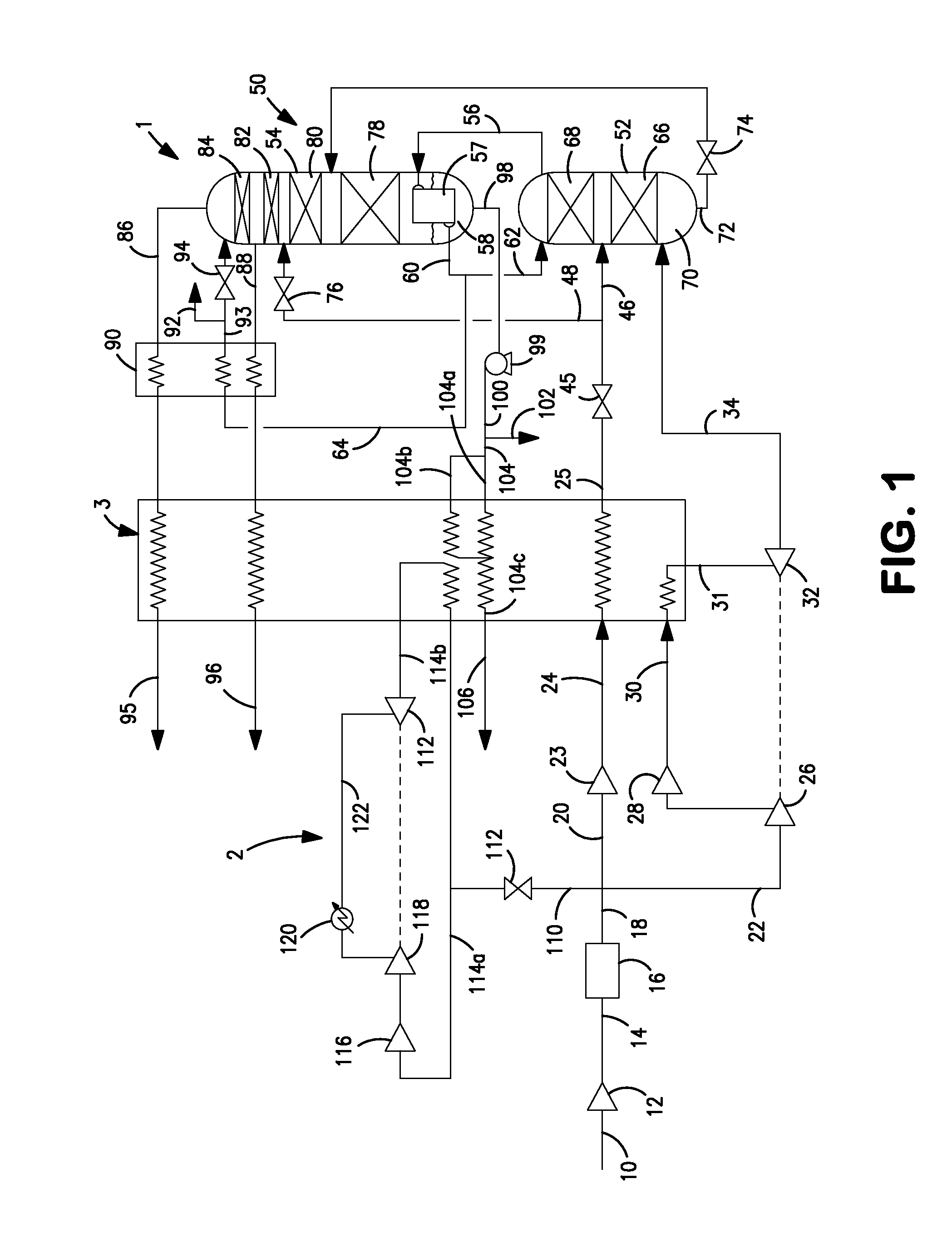
[0028]With reference to FIG. 1, a cryogenic air separation plant 1 is illustrated that is integrated with a closed loop refrigeration system 2, discussed hereinafter, to increase production of liquid products. This integration is accomplished with the use of a heat exchanger 3 that is provided with layers that allow subsidiary streams of pumped liquid oxygen to reach a temperature that exceeds either at the dew point or the critical temperature of the pumped liquid oxygen and then combine such subsidiary streams to leave regions of layers free for warming a refrigerant stream produced in the closed loop refrigeration cycle. It is understood, however, that the integration of air separation plant 1 and closed loop refrigeration system 2 is but one application of the present invention.

[0029]As to air separation plant 1, an air stream 10 is introduced into a cryogenic air separation plant 1 to separate oxygen from the nitrogen. Air stream 10 is compressed within a first compressor 12 to...


PUM


Abstract

The present invention relates to a method and apparatus for producing a pressurized product stream product by cryogenic rectification. A main heat exchanger, used in the cryogenic rectification, warms a pumped product stream composed of oxygen-rich or nitrogen-rich liquid and thereby produces the pressurized product stream. Layers of the main heat exchanger are designed such that a reduction in the heat transfer area provided within the main heat exchanger for warming the pumped product stream occurs at a location at which the temperature of the pumped product stream exceeds either the critical or a dew point temperature of such stream. The reduction in heat transfer area leaves regions of the layers able to heat or cool another stream that is used in connection with the cryogenic rectification. Such other stream can be a refrigerant stream that allows the introduction of additional refrigeration to increase production of liquid products.

Description

FIELD OF THE INVENTION [0001]The present invention relates to a method and apparatus for producing a pressurized product stream by cryogenic rectification in which the product stream is formed from a pumped product stream composed of oxygen-rich or nitrogen-rich liquid that is warmed within a main heat exchanger that is used in connection with the cryogenic rectification. Even more particularly, the present invention relates to such a method and apparatus in which the pumped product is warmed within layers of the main heat exchanger that are designed to both warm the pumped liquid product and warm or cool another stream.BACKGROUND OF THE INVENTION [0002]Oxygen is separated from oxygen containing feeds, such as air, through cryogenic rectification. In cryogenic rectification, the feed is compressed, if not obtained in a pressurized state, purified of contaminants and then cooled in a main heat exchanger to a temperature suitable for its rectification. The cooled feed is then introduc...

Claims


Application Information

Patent Timeline
Patent Type & Authority Applications(United States)
IPC IPC(8): F25J3/02
CPCF25J3/0409F25J3/0486F25J3/04278F25J3/04296F25J3/04412F25J5/002F25J2245/40F25J2270/14F25J2270/40F25J2290/32F28D9/0093F28F9/026F25J3/04175F25J2270/902F25J3/042
Inventor HOWARD, HENRY EDWARDJIBB, RICHARD JOHNPARSNICK, DAVID ROSSSKARE, TODD ALAN
Owner PRAXAIR TECH INC
Why Eureka
Try Eureka