Speed change device of a transmission

a technology of speed change device and transmission, which is applied in the direction of gearing control, mechanical equipment, transportation and packaging, etc., can solve the problems of power interruption, reduce the size of the drive unit, reduce the outer diameter of the cylindrical drum, and reduce the rotational torque required

Active Publication Date: 2014-01-28
ISUZU MOTORS LTD
View PDF28 Cites 10 Cited by
  • Summary
  • Abstract
  • Description
  • Claims
  • Application Information

AI Technical Summary

Benefits of technology

[0022]The speed change device of the invention has a cylindrical drum that is reciprocally movable in the axial direction and is rotatably supported, the cylindrical surface of the cylindrical drum forming a plurality of drum grooves to which the fork operation members coupled to a plurality of forks are fitted. The drum grooves are each forming small width portions and large width portions continuously in the circumferential direction. In the plurality of drum grooves, the small width portions and the large width portions are so formed that the fork operation member positioned at the small width portion is shifted depending upon the rotation of the cylindrical drum. The small width portion in the drum groove has both sides thereof perpendicular to the axial direction of the cylindrical drum and has the width in the axial direction nearly equal to that of the fork operation member while the large width portion has the width in the axial direction which is wider than that of the fork operation member. Therefore, when the cylindrical drum moves in the axial direction, only the fork operation member positioned at the small width portion, among the plurality of fork operation members, moves in the axial direction together with the cylindrical drum while the other fork operation members positioned at the large width portions do not move but stay at those positions.
[0023]In shifting the gear of the transmission, the cylindrical drum is rotated by a drive unit such as a motor so that the fork operation member coupled to the fork to be shifted is positioned at the small width portion in the drum groove. Next, the cylindrical drum is displaced in the axial direction by the other drive unit such as a motor, whereby the fork operation member positioned at the small width portion moves in the axial direction, and the fork coupled to the fork operation member is shifted.
[0024]According to the speed change device of the present invention as described above, the select operation for selecting the fork that is to be shifted is executed by the rotation of the cylindrical drum, and the shift operation for shifting the fork is executed by the motion of the cylindrical drum in the axial direction; i.e., the select operation and the shift operation are executed independently by the cylindrical drum as it rotates and reciprocally moves. Namely, according to the present invention, unlike the cam drum in the conventional speed change device, the cylindrical drum does not select the fork while at the same time shifting it fork in the axial direction by the rotation thereof. Therefore, the drum grooves formed in the cylindrical surface of the cylindrical drum do not have to be provided with tilted portions for moving the fork in the axial direction. It is, therefore, allowed to greatly decrease the outer diameter of the cylindrical drum as compared to that of the conventional cam drum, to decrease the rotational torque required for the rotation and, hence, to decrease the size of the drive unit such as a motor. At the same time, it is allowed to decrease the size of the whole speed change device, to decrease the inertial weight and to improve the operability of the transmission.
[0025]In the speed change device of the invention, further, the fork operation member positioned at the small width portion of the drum groove is moved in the axial direction by the cylindrical drum that reciprocally moves. Therefore, both sides of the small width portion of the drum groove are forming wall surfaces perpendicular to the axial direction of the cylindrical drum. Unlike the cam grooves in the conventional cam drum, the drum grooves in the cylindrical drum of the present invention contain no tilted portion along which the fork operation member slides in contact therewith. Therefore, the speed change device of the present invention alleviates the slide resistance at the time of shifting the fork operation member or a decrease in the transmission efficiency caused thereby. The fork operation member moves in the axial direction of the cylindrical drum being pushed onto the wall surface perpendicular to the axial direction, and no sliding motion takes place between the two. Therefore, no wear occurs in the contact surfaces.
[0026]In the invention of claim 2, the cylindrical drum is fitted onto the rotary drum sleeve so as to slide but so as not to rotate, and the threaded shaft is arranged penetrating through the drum sleeve in concentric therewith. The cylindrical drum is screw-coupled to the threaded shaft. The threaded shaft constitutes a so-called feed screw mechanism. Upon rotating the drum sleeve, the cylindrical drum rotates, too, to execute the select operation. Upon rotating the threaded shaft, the cylindrical drum reciprocally moves in the axial direction to execute the shift operation. The speed change device as a whole is compact in size since the drum sleeve and the cylindrical drum are arranged in concentric with the threaded shaft that rotates. Besides, since the cylindrical drum reciprocally moves relying on the rotation of the threaded shaft, no mechanism is required for converting the rotary motion into the reciprocal motion. Therefore, the drive unit such as motor can be easily laid out.
[0027]As in the invention of claim 3, when the plurality of fork operation members are linearly arranged in the axial direction of the cylindrical drum, the fork operation members are all aligned in the axial direction of the cylindrical drum enabling the speed change device to be more compactly fabricated and facilitating the assembling operation. When the fork operation members are linearly arranged as in the invention of claim 4, one of the plurality of fork operation members is provided with a shift rod that extends in the axial direction of the cylindrical drum and is supported so as to slide, a fork is coupled to the shift rod, and the other forks are fitted to the shift rod to constitute the speed change device. This makes it possible to simplify the device for supporting the forks and the fork operation members in a manner to move in the axial direction.

Problems solved by technology

When the speed-changing sleeve SV is at its neutral position, however, the meshing is released, and the transmission of power is interrupted.

Method used


Image

  • Speed change device of a transmission
  • Speed change device of a transmission
  • Speed change device of a transmission

Examples


Embodiment Construction

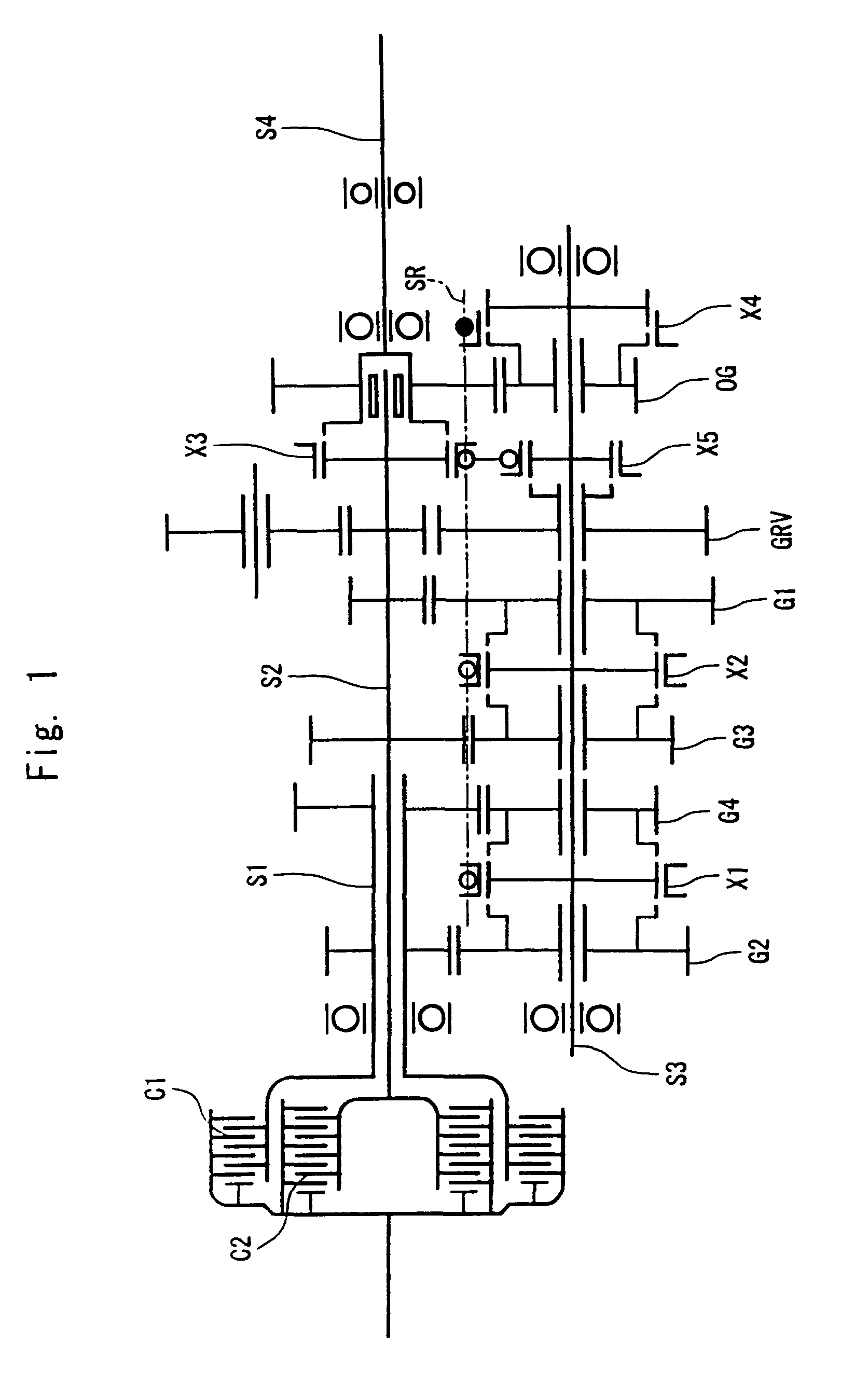
[0046]An embodiment of the speed change device of the invention will now be described with reference to the drawings. In this embodiment, the invention is adapted to the speed change device of the dual clutch type transmission. First, the structure and operation of the dual clutch type transmission will be briefly described with reference to FIG. 1.

[0047]In the dual clutch type transmission, there are arranged a first input shaft S1 and a second input shaft S2 of a double tubular structure, the second input shaft S2 extending rearward penetrating through the first hollow input shaft S1. At the front parts of the input shafts, there are provided a first clutch C1 and a second clutch C2 of the type of wet multiple disks arranged in concentric, the input sides of the respective clutches being connected to an engine output shaft. An intermediate shaft (counter shaft) S3 is installed in parallel with these input shafts, and an output shaft S4 of the transmission continuous to a propeller...


PUM


Abstract

A speed change device for shifting the gear of a transmission by using a cylindrical drum that reciprocally moves and rotates, featuring the structure of a compact size and excellent operability. To execute the shifting operation, the speed change device of the invention uses a cylindrical drum 4 that reciprocally moves in the axial direction and is rotatably supported. Fork pins FP1 to FP4 coupled to a plurality of forks of the transmission are fitted into drum grooves 41 to 44 formed in the cylindrical surface of the cylindrical drum. In each drum groove, there are formed small width portions of a width nearly equal to that of the fork pin and large width portions wider than the small width portions in a manner that the fork pin positioned at the small width portion is shifted. To shift the gear, the cylindrical drum 4 is rotated by a select motor 6 to select the fork pin positioned at the small width portion. Next, a threaded shaft 1 is rotated by a shift motor 7 to move the cylindrical drum 4 in the axial direction to thereby shift the selected fork pin.

Description

TECHNICAL FIELD[0001]This invention relates to a speed change device for shifting the gear of a transmission of a vehicle. More specifically, the invention relates to a speed change device suited for a vehicle on which an automatic transmission is mounted.[0002]As the power transmission devices of vehicles, there have been proposed various kinds of speed-changing devices for automatically carrying out the operation of the transmission requiring no clutch operation for easy driving and for reducing fatigue to the drivers. A representative example may be an automatic transmission (AT) incorporating a torque converter and planetary gears. Among the automatic speed-changing devices, however, there exists a power transmission device that uses a transmission of the type of parallel shaft gear mechanism similar to the manual transmission (MT). In this power transmission device, the gear is shifted responsive to a driver's instruction or an instruction from an electronic control device such...

Claims


Application Information

Patent Timeline
Patent Type & Authority Patents(United States)
IPC IPC(8): B60K20/00F16H59/04
CPCF16H2061/2884F16H61/32F16H63/18F16H61/28F16H2063/025F16H2061/2869Y10T74/20177
Inventor AKASHI, KOUHEIIKEDA, TADASHI
Owner ISUZU MOTORS LTD
Why Eureka
Try Eureka