Method, apparatus, and system for refueling hydrogen vehicles

a hydrogen vehicle and hydrogen technology, applied in the field of hydrogen vehicle refueling, can solve the problems of substantial maintenance requirements, substantial skill and care in sitting, sizing, installation and commissioning, and the inability to meet the needs of hydrogen storage on hydrogen powered vehicles

Active Publication Date: 2019-03-26
ONEH2 INC
View PDF8 Cites 7 Cited by
  • Summary
  • Abstract
  • Description
  • Claims
  • Application Information

AI Technical Summary

Problems solved by technology

Alternative forms of storing the hydrogen on the hydrogen powered vehicle have not proven commercially important, such as cryogenic liquid, cryogenic gas, metal or chemical hydrides, etc.
First, they require that a compressor be installed at the point of refueling.
Compressors suitable for high pressure hydrogen service, though known and quite proven, have substantial requirements for ongoing maintenance, and require substantial skill and care in siting, sizing, installation and commissioning.
Although all of these tasks are readily accomplished, they impose substantial burdens in terms of financial cost, time required to bring a refueling station into service, and the degree of skill and number of staff needed to successfully support the ongoing operation of the refueling facility.
Likewise, due to the substantial size of the compressor itself, the cascade cylinders, the dispenser, and the truck delivering the hydrogen by trailer equipped with cryogenic storage or compressed gas cylinders, the area required for the refueling operation is undesirably large.
It may not be feasible to site all of the needed equipment at a location which otherwise would be provided with hydrogen refueling.
Furthermore, the cost and time needed for the solution described above is difficult to justify unless a large number of hydrogen powered vehicles is present.
Likewise, if refueling hydrogen powered vehicles is discontinued for any reason, all of the site preparation costs and time invested in the installation of the traditional solution are lost.
This results in a need to either have extreme certainty that refueling will not be discontinued, or the need to repay the costs of the installation very rapidly.
Although this advantageously maximizes the withdrawal of hydrogen from the transportable assemblies, it disadvantageously requires a larger amount of working space in which to store the multiple assemblies.
Although the '682 patent mentions the possibility that cascade filling might be used in combination with the multiple transportable assemblies, it does not provide significant guidance regarding a method of cascade filling, or how the configuration of the cascade might be employed to optimize the utility of the transportable assemblies.
For applications requiring smaller total quantities of hydrogen, this disadvantageously increases the cost and complexity of the transportable assemblies, and requires that they be of a fixed, pre-manufactured configuration.
The combination of these features disadvantageously increases the cost and complexity of the deliverable solution.
Furthermore, in situations where the demand for hydrogen is variable over time, it may be economically-undesirable to provide the single fixed size of transportable system, as the transportable system becomes the minimum unit of supply.

Method used


Image

  • Method, apparatus, and system for refueling hydrogen vehicles
  • Method, apparatus, and system for refueling hydrogen vehicles
  • Method, apparatus, and system for refueling hydrogen vehicles

Examples


Embodiment Construction

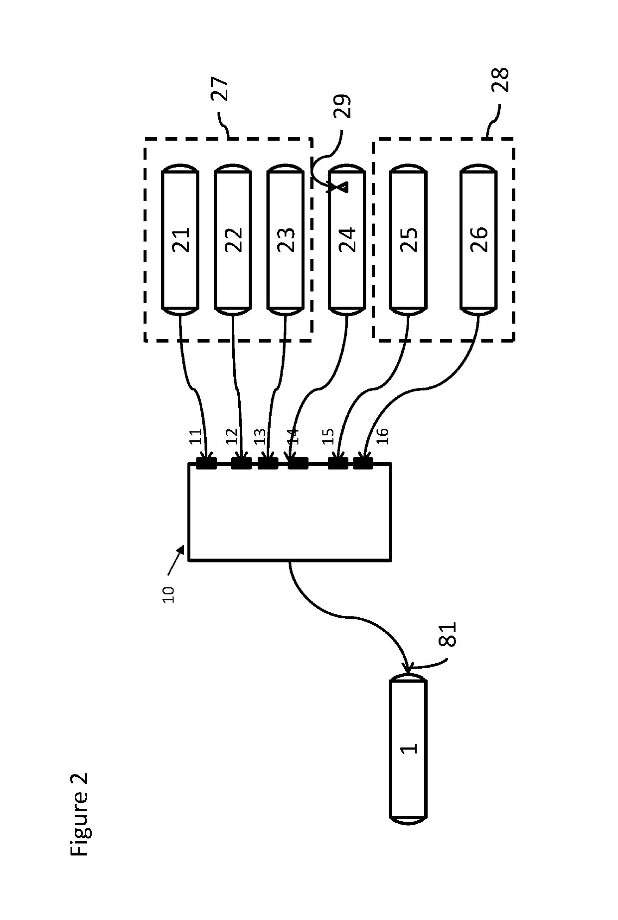
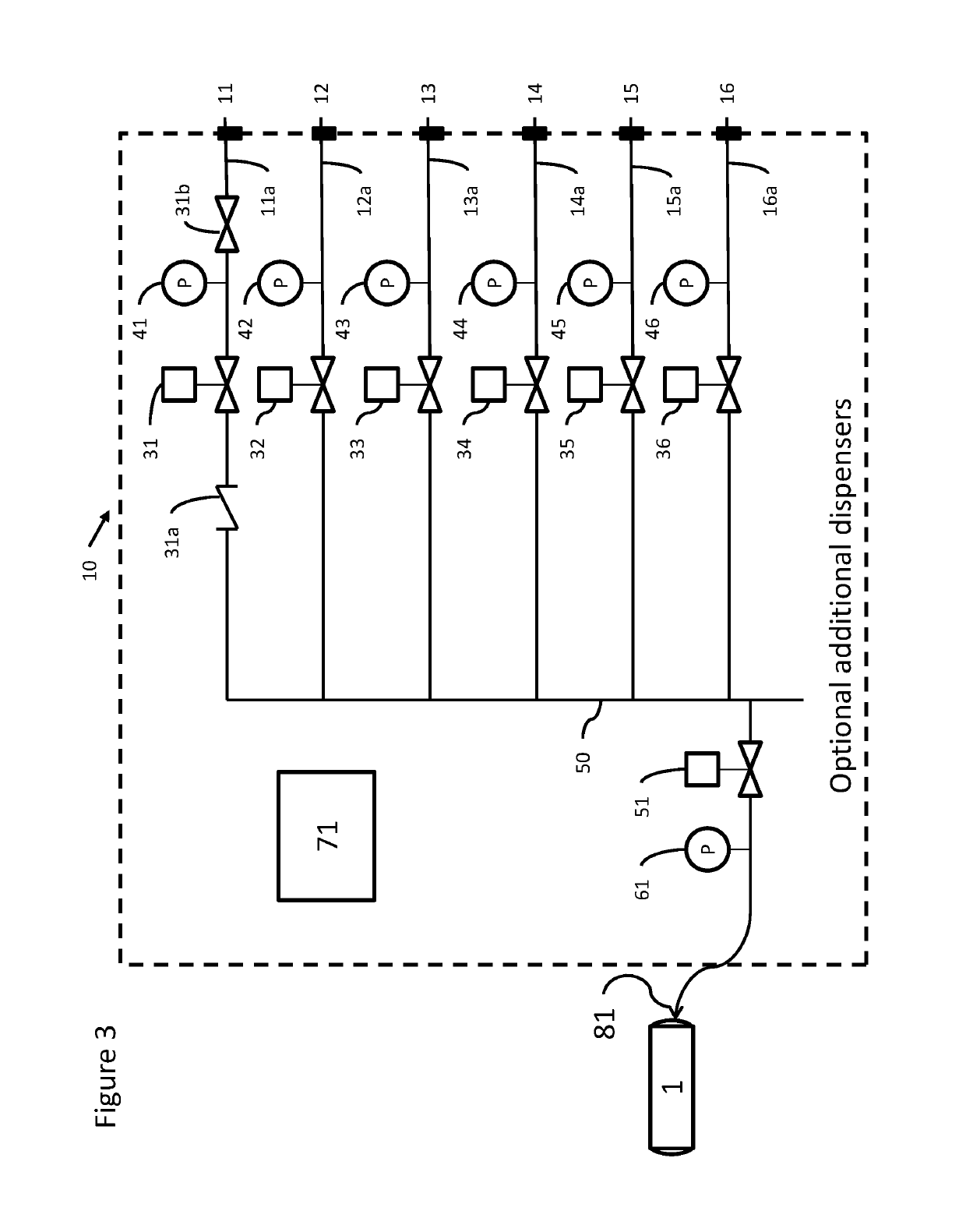
[0022]Described herein are a method and an apparatus for refueling hydrogen vehicles at a point remote from the hydrogen production which uses a cascade of compressed hydrogen sources which can vary in complexity from the extreme of a single source, to the maximum number of sources for which the dispenser apparatus is manufactured. The quantity and size of delivered gas sources may be adjusted to suit the volume of demand and the available equipment and quantity of compressed gas without any alteration to the refueling system.

[0023]An embodiment of the present invention provides a method of refueling hydrogen powered vehicles that employs delivered pressure cylinders that are pressurized to a pressure that is preferably greater than the intended vehicle fill pressure, connecting the delivered cylinders to a dispenser apparatus, and refilling vehicles without recompression at the refueling site from cylinders via the dispenser apparatus. The dispenser apparatus can be either transpor...


PUM


Abstract

A dispenser apparatus that includes a first cascade stage having a first connector configured to connect to and disconnect from a first gas storage vessel, and a first conduit connected to the first connector and having a first valve and a first pressure measuring device, and a second cascade stage having a second connector configured to connect to and disconnect from a second gas storage vessel, and a second conduit connected to the second connector and having a second valve and a second pressure measuring device. A common flow path is fluidly connected to the conduits, and has a dispensing nozzle to connect to a vehicle during refueling. A controller is provided to control the first and / or second valve(s) to perform refueling using gas stored in at least one of the first and second gas storage vessels based on pressure measurements of the first and / or second pressure measuring device(s).

Description

CROSS-REFERENCE TO RELATED APPLICATION[0001]The present application claims priority to U.S. Provisional Application No. 62 / 238,785, filed on Oct. 8, 2015, the entire contents of which are herein incorporated by reference.BACKGROUND OF THE INVENTIONField of the Invention[0002]The present invention relates to refueling of hydrogen vehicles.Discussion of the Background[0003]Hydrogen fueled vehicles are known, and have been extant for many years. The most common type of hydrogen fueled vehicle uses compressed gaseous hydrogen storage on the vehicle, and is fueled with gaseous hydrogen at the point of dispensing. Alternative forms of storing the hydrogen on the hydrogen powered vehicle have not proven commercially important, such as cryogenic liquid, cryogenic gas, metal or chemical hydrides, etc. Typically, the point of refueling for hydrogen vehicles is remote from the point of production of hydrogen, requiring the hydrogen to be transported to the point of refueling.[0004]Solutions to...

Claims


Application Information

Patent Timeline
Patent Type & Authority Patents(United States)
IPC IPC(8): F17C5/06
CPCF17C5/06F17C2205/0142F17C2205/0153F17C2205/054F17C2205/058F17C2265/065F17C2223/036F17C2225/036F17C2227/042F17C2250/032F17C2250/0434F17C2221/012F17C2205/0146F17C2205/0326F17C2205/0332F17C2223/0123F17C2223/035F17C2225/0123F17C2227/043F17C2250/043F17C2270/0168Y02E60/32
Inventor DAWSON, PAUL A.LOMAX, FRANKLIN D.LEMOS, RAFAEL S.HOUNG, DAVID
Owner ONEH2 INC
Why Eureka
Try Eureka